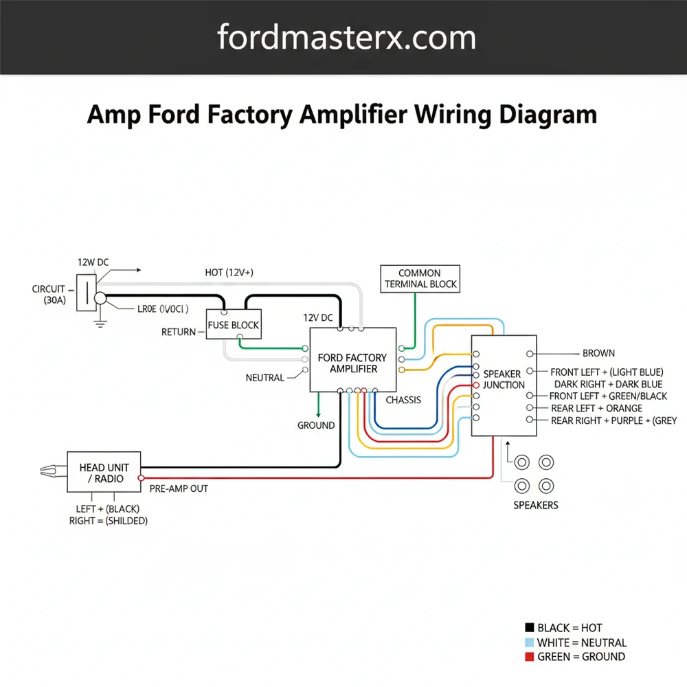
Ford Factory Amplifier Wiring Diagram: Easy Setup Guide
This diagram provides the pinout for power, signal, and speaker connections. It identifies the 12V hot wire, ground wire, and audio inputs. By locating the common terminal and signal paths, you can successfully bypass or replace the unit, ensuring every speaker receives the correct frequency and amplified signal.
📌 Key Takeaways
- Identifies the specific pin functions for the factory Ford audio harness
- The 12V hot wire is the most critical connection for unit power
- Always disconnect the battery before tampering with factory wiring
- Helps integrate aftermarket processors with factory speaker signals
- Used primarily for bypassing factory DSP or adding a subwoofer
Locating and interpreting the correct amp ford factory amplifier wiring diagram is a critical step for any car audio enthusiast looking to upgrade their vehicle’s sound system. Whether you are performing a complete bypass or simply integrating a new subwoofer, understanding how the factory signals are routed ensures you don’t accidentally damage your vehicle’s sensitive electronics. This guide provides a detailed breakdown of the wiring architecture used in Ford’s premium audio systems. You will learn how to identify input and output channels, manage power distribution, and ensure that your new equipment interfaces perfectly with the existing harness.
The architecture of a Ford factory amplifier typically involves two or three primary connectors, each serving a specific function within the audio network. The main amp ford factory amplifier wiring diagram reveals a complex web of signals that handle everything from low-level audio data to high-current power delivery. Usually, the largest connector is responsible for the speaker outputs, while a smaller connector manages the input signals from the head unit.
In these diagrams, the color-coding is highly specific. For instance, a solid color often represents the positive lead, while the same color with a black or white stripe indicates the negative lead. However, it is important to note that Ford often utilizes a twisted-pair configuration for signal wires to minimize electromagnetic interference. The diagram also illustrates the 12V constant power source, often referred to as the hot wire in traditional electrical terms, which requires a specific gauge of wire to handle the current load without significant voltage drop.
Variations exist between different trim levels, such as the base system versus the Sony or B&O premium packages. In premium setups, the amplifier acts as a digital signal processor (DSP), receiving a fixed-level signal and adjusting volume via digital commands. This means the common terminal for your ground wire must be exceptionally clean to prevent the introduction of alternator whine. The diagram placeholder below represents the typical pinout arrangement found in these modules.
(Visual Representation of 24-Pin Connector A and 16-Pin Connector B)
Pin 1: Power (Hot) | Pin 2: Ground (Common)
Pin 3-10: Speaker Outputs (FL, FR, RL, RR)
Pin 11-16: CAN-BUS / Remote Turn-on (Voltage Trigger)
Most Ford amplifiers are located either behind the rear quarter panels or tucked under the center console. Always verify the pinout with a multimeter to ensure the voltage levels match the diagram expectations before making permanent cuts.
To successfully use the amp ford factory amplifier wiring diagram for your installation, you must follow a methodical sequence to avoid short circuits or phase issues.
Step 1: Preparation and Tool Gathering
Before touching any wires, ensure you have a high-quality digital multimeter, wire strippers, and a soldering iron or high-quality crimp connectors. You will also need to reference the specific wire gauge requirements for your aftermarket components to ensure they match or exceed the factory specifications.
Step 2: Disconnecting the Power
Safety is paramount. Disconnect the negative battery terminal to prevent any accidental shorts while you are probing the harness. This protects the vehicle’s Body Control Module (BCM) and the audio head unit from sudden spikes in current.
Step 3: Identifying the Main Power and Ground
Consult your diagram to locate the primary power source, often labeled as the hot wire. This is typically a thick 10 or 12-gauge wire. Similarly, identify the ground wire which connects to the common terminal of the vehicle’s chassis. Using a brass screw for a new ground point is common practice if the factory ground is insufficient for a high-powered aftermarket amp.
Step 4: Locating the Signal Inputs
Ford systems often use a low-level differential signal. In your diagram, look for the traveler wire pairs that bring the signal from the radio to the amp. Unlike a standard home neutral wire, these car audio negatives carry a signal and should not be grounded directly to the chassis.
Step 5: Mapping the Speaker Outputs
This is where the amp ford factory amplifier wiring diagram is most useful. Each speaker—tweeters, door woofers, and center channel—will have a dedicated pair of wires. Use a 9V battery to “pop” the speakers momentarily to verify their location. You will touch the positive and negative of the battery to the wires; a small audible pop confirms you have the correct pair for that specific speaker.
Step 6: Integrating the Remote Turn-On
Aftermarket amplifiers require a 12V trigger to turn on. Look at your diagram for a wire that shows voltage only when the ignition or radio is turned on. If your Ford uses a CAN-BUS system, you may not find a traditional 12V remote wire; in this case, you will need a signal-sensing line output converter.
Step 7: Testing the Connections
Reconnect the battery and use your multimeter to check the voltage at the amplifier’s power terminals. Ensure the signal wires are correctly seated. Check for continuity between the ground wire and the common terminal on the chassis.
Step 8: Finalizing and Securing
Once functionality is confirmed, use heat-shrink tubing to protect all connections. Avoid using electrical tape alone, as vehicle heat can cause the adhesive to fail over time, leading to exposed wires and potential shorts.
Modern Ford vehicles often use Start-Stop technology. If your wiring does not account for the voltage dip during engine cranking, your aftermarket amplifier may shut down or reboot every time the car restarts at a stoplight.
Even with a perfect amp ford factory amplifier wiring diagram, issues can arise during the installation process. One of the most common problems is “alternator whine,” a high-pitched noise that fluctuates with engine RPM. This is usually caused by a ground loop, where the ground wire is not connected to a clean, paint-free common terminal.
Another frequent issue is the “no sound” condition. This often happens when the remote turn-on wire is not receiving the correct voltage to trigger the amplifier. If your diagram shows a traveler wire for data (like CAN+ and CAN-), do not tap into these for audio signals, as it can cause the entire vehicle’s communication network to crash, leading to dashboard error lights.
If you notice that your speakers are moving but the sound is “thin” or lacks bass, you may have reversed the polarity on one of the channels. Check your diagram again to ensure every positive lead is matched correctly. If the voltage at the amplifier drops significantly when the volume is turned up, your wire gauge may be too small for the current demand, requiring a thicker power cable.
- ✓ Issue: Constant Hiss – Solution: Lower the gain settings on the amplifier.
- ✓ Issue: Amp Clipping – Solution: Verify the hot wire is providing a steady 12.6V to 14.4V.
- ✓ Issue: Pop on Startup – Solution: Install a delay module on the remote voltage line.
When working with an amp ford factory amplifier wiring diagram, the difference between a professional-grade install and a DIY failure often comes down to the details. Always use high-quality OFC (Oxygen-Free Copper) wire rather than CCA (Copper Clad Aluminum). While CCA is cheaper, it has higher resistance and can lead to voltage drops that hinder the performance of your factory or aftermarket amplifier.
For maintenance, periodically check the tightness of your ground connection. If you used a brass screw into the chassis, ensure no corrosion has formed around the contact point. Using a small amount of dielectric grease can help prevent oxidation in damp environments.
If you are looking to save costs, consider using a T-harness. A T-harness plugs directly into the factory connections, allowing you to tap into the speaker signals without cutting the original factory wires. This preserves the resale value of the vehicle and makes it easy to revert to stock if you sell the car.
Label every wire as you identify it. Using a simple piece of masking tape and a marker to label the “Front Left Positive” or “Main Hot Wire” will save you hours of frustration if you have to troubleshoot the system later on.
Lastly, always ensure your fuse is placed within 18 inches of the battery on the main power wire. This protects the entire length of the cable. Following the amp ford factory amplifier wiring diagram precisely while adhering to these best practices will result in a reliable, high-fidelity audio experience that brings out the best in your vehicle’s cabin acoustics. With the right tools and a clear understanding of the voltage and gauge requirements, your Ford audio upgrade will be a resounding success.
Step-by-Step Guide to Understanding the Ford Factory Amplifier Wiring Diagram: Easy Setup Guide
Identify the factory harness connectors by comparing them to your specific Ford model’s pinout diagram.
Locate the ground wire and ensure it is securely connected to a clean, unpainted metal surface on the chassis.
Understand how the remote signal acts as a traveler wire to trigger the amplifier’s turn-on sequence when the radio starts.
Connect the 12V hot wire to the battery using an appropriate inline fuse to protect the circuit from surges.
Verify that the common terminal for the speaker negatives is properly isolated to prevent short-circuiting the internal amp chips.
Complete the installation by testing each speaker channel for correct polarity and clear audio reproduction before reassembling the interior.
Frequently Asked Questions
Where is the Ford factory amplifier located?
The amplifier location varies by model; common spots include behind the glovebox, under the center console, or mounted in the rear trunk panels. In many Ford SUVs, it is tucked behind the right-side cargo trim. Consult your specific vehicle’s layout to avoid unnecessary dash disassembly during your installation.
What does this wiring diagram show?
This diagram maps the electrical path from the head unit to the speakers. It details the high-level and low-level inputs, the 12V power hot wire, and the ground wire. It ensures you can match the correct polarity for each speaker channel, preventing phase issues and maintaining optimal audio quality.
How many connections does the Ford amplifier have?
Most modern Ford amplifiers feature two to three main harnesses, totaling 16 to 24 pins. These connections include the main power supply, the common terminal for shared grounds, and individual twisted pairs for speaker outputs. Luxury trims like Sony or B&O systems often feature higher pin counts for center channels.
What are the symptoms of a bad factory amplifier?
A failing amplifier typically results in a complete loss of sound despite the radio powering on. You may also notice popping noises, static in one channel, or the unit becoming excessively hot. Blown fuses or a loose ground wire are often the primary culprits for intermittent audio output failures.
Can I install an aftermarket amp myself?
Yes, you can install an aftermarket amp by using a T-harness that plugs into the factory wiring. This allows you to tap into the signal without cutting the hot wire or factory loom. Unlike household wiring that uses a neutral wire, you must ensure a solid chassis ground for safety.
What tools do I need for this task?
You will need a digital multimeter to test voltage, a set of socket wrenches for battery disconnection, and plastic trim removal tools. A wire stripper and soldering iron are recommended for permanent connections. Using a diagram helps you identify which traveler wire carries the remote turn-on signal for the amp.


