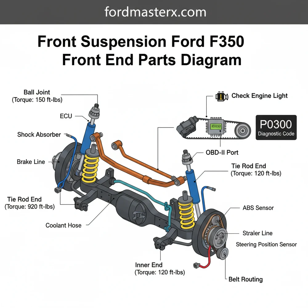
Ford F350 Front End Parts Diagram: Suspension Guide
The front suspension Ford F350 front end parts diagram illustrates the layout of critical components like ball joints, tie rods, track bars, and shocks. It helps owners identify worn steering links or suspension bushings to maintain heavy-duty stability, ensuring safe towing by providing a visual map of the entire front assembly.
📌 Key Takeaways
- Identifies the complex geometry of heavy-duty solid axle suspension.
- The track bar is the most critical component for preventing steering instability.
- Always support the vehicle frame with high-capacity jack stands for safety.
- Check for uneven tire wear to quickly spot alignment or bushing failure.
- Use this diagram when diagnosing ‘Death Wobble’ or front-end clunking.
The Ford F-350 Super Duty is legendary for its hauling capacity and rugged durability, but the heavy-duty nature of this truck puts immense strain on its front suspension system. Whether you are daily driving, towing a fifth-wheel, or navigating off-road terrain, the front end of an F-350—particularly the 4WD solid axle setup used from 2005 onwards—is a complex assembly of high-torque components. Understanding a front-end parts diagram is the first step for any DIY enthusiast looking to maintain steering precision, eliminate the dreaded “death wobble,” or perform a complete rebuild. This guide breaks down the anatomy of the Ford F-350 front suspension, providing the technical details and practical insights needed to navigate a parts diagram and execute repairs successfully.
Main Components and Features of the F-350 Front End
The F-350 front suspension varies slightly depending on whether the truck is 2WD or 4WD and the specific model year. However, for most modern Super Duty trucks (specifically those with the coil spring front suspension), the system is built around a solid front axle. Below are the primary components found in a standard front-end parts diagram:
- Track Bar (Panhard Bar): This is arguably the most critical component for lateral stability. It connects the axle to the frame, preventing the axle from shifting side-to-side. On a diagram, it looks like a thick, bent steel bar with a large bushing on the frame side and a ball joint on the axle side.
- Drag Link: This component transmits steering motion from the pitman arm (connected to the steering box) to the passenger-side steering knuckle. It is the long bar that runs diagonally across the front end.
- Tie Rod Assembly: The tie rods connect the left and right steering knuckles, ensuring that both wheels turn in unison. The assembly consists of an inner and outer tie rod connected by an adjusting sleeve.
- Ball Joints (Upper and Lower): These are the pivot points for the steering knuckles. Each side has an upper and lower ball joint. In an exploded diagram, these are shown pressed into the “C” shaped ends of the axle housing.
- Radius Arms: These massive steel arms run from the axle back to the frame. They control the fore-and-aft movement of the axle and maintain the caster angle. They are secured by large 24mm or 30mm bolts and heavy-duty rubber or polyurethane bushings.
- Steering Stabilizer: Essentially a horizontal shock absorber, the stabilizer is mounted between the frame (or drag link) and the axle to dampen vibrations and road kickback.
- Hub Assembly and Bearings: On 4WD models, the hub assembly includes the wheel bearings and the vacuum-actuated locking hub mechanism. This unit also houses the ABS wheel speed sensor.
How to Read and Use a Front End Parts Diagram
Reading a Ford F-350 parts diagram requires an understanding of “exploded views.” In these diagrams, parts are shown detached from one another but aligned in the order of assembly. This is vital for seeing how washers, nuts, and cotter pins are sequenced.
To use a diagram effectively for a DIY project, follow these steps:
- Identify the Reference Numbers: Most diagrams use callout numbers (e.g., 3A131 for a tie rod end) rather than full part numbers. You must cross-reference these callout numbers with a parts list specific to your VIN to get the exact Ford Engineering number.
- Note the Orientation: Diagrams usually show the front end as if you are standing in front of the bumper looking back. The “Right Hand” (RH) side refers to the passenger side, and the “Left Hand” (LH) side refers to the driver side.
- Locate Hardware Sequences: Pay attention to the location of castle nuts and cotter pins. In an F-350, many steering components use tapered seats. The diagram will show the taper direction, which is essential for ensuring you don’t install a part upside down.
- Electrical and Vacuum Lines: On 4WD models, the diagram will show the vacuum lines for the auto-locking hubs. Look for the black rubber hoses and the ABS wire routing. ABS wires typically feature a Black/Blue or Black/Green wire pair depending on the production year, and the diagram will show the specific clips used to secure them to the brake lines.
Practical Tips for DIY Front End Work

Working on an F-350 front end requires heavy-duty tools. These are not small passenger car components; they are high-torque, heavy-mass parts.
- Torque is King: The F-350 has some of the highest torque requirements of any consumer vehicle. For example, the track bar bolt on a 2011-2016 F-350 requires a staggering 406 lb-ft of torque. Ensure you have a 3/4-inch drive torque wrench capable of reaching these specs.
- Use a Ball Joint Press: Do not attempt to “hammer out” F-350 ball joints. The axle C-mounts are thick, and the joints are pressed in with thousands of pounds of force. Rent or buy a heavy-duty C-frame press specifically rated for 4WD trucks.
- Measure Before Disassembly: Before removing tie rods or drag links, measure the “center-to-center” distance between the grease zerks or the total length of the assembly. This will allow you to get the alignment “close enough” to drive the truck to a professional alignment shop after the repair.
- The “Dry Steering” Test: If you aren’t sure which part is bad, have an assistant sit in the truck and turn the steering wheel back and forth rapidly while the truck is on the ground. Watch the joints in the diagram. Any “pop” or lateral movement in a joint indicates it is worn out.
Troubleshooting Common F-350 Front End Issues
The F-350 front end is prone to several specific issues that can be diagnosed by cross-referencing your symptoms with the parts diagram.
1. The Death Wobble
This is a violent shaking of the front end after hitting a bump at highway speeds. According to the parts diagram, the primary culprits are the Track Bar Bushing and the Track Bar Ball Joint. If the track bar has even 1/16th of an inch of play, the axle can oscillate, causing the wobble. Check the steering stabilizer as well; while it doesn’t cause the wobble, a worn stabilizer fails to mask it.
2. Uneven Tire Wear (Cuppy or Inner Edge Wear)
If you see “sawtooth” wear on your front tires, look at the Upper and Lower Ball Joints on the diagram. Worn ball joints allow the wheel to tilt (camber change), leading to rapid tire destruction. Another culprit is the Toe-In setting, which is adjusted via the tie rod sleeves.
3. “Clunking” Over Bumps
If you hear a heavy clunk under your feet, look at the Radius Arm Bushings and the Sway Bar End Links. The sway bar links are relatively small (usually requiring an 18mm socket) but take a lot of abuse. When the internal ball-and-socket joint wears out, it creates a metallic knocking sound that resonates through the frame.
4. Steering Wander
If the truck feels “darty” or requires constant correction to stay in a lane, look at the Steering Gear Box and the Drag Link. Excessive play in the steering box sector shaft or a loose pitman arm nut (which is a massive 42mm or 46mm nut depending on the year) are common causes of wandering.
- Track Bar Nut: 30mm or 1-3/16″
- Tie Rod End Nut: 21mm or 24mm (with cotter pin)
- Wheel Lug Nuts: 21mm (8-lug pattern, 165 lb-ft torque)
- Vacuum Line Diameter: 1/8″ or 5/32″ (standard vacuum tubing)
Final Thoughts for the DIYer
Working on a Ford F-350 front end is a labor-intensive but rewarding process. By using a parts diagram as your map, you can identify precisely which components are contributing to poor handling or noise. Always prioritize the track bar and ball joints, as these are the foundation of the Super Duty’s steering geometry. Once your parts are replaced, remember that a professional “thrust angle” alignment is mandatory. The solid axle design means that even small changes in one component can affect the entire steering rack’s geometry. With the right tools and a clear understanding of the assembly, you can restore your F-350 to its original factory-fresh steering feel and ensure it remains safe for the heaviest loads.
Step-by-Step Guide to Understanding the Ford F350 Front End Parts Diagram: Suspension Guide
Identify the components on the front suspension Ford F350 front end parts diagram.
Locate the steering linkages, including the drag link, tie rods, and track bar.
Understand how each joint connects to the steering knuckle and the front axle.
Apply the correct torque spec to every bolt to ensure the assembly remains secure.
Verify that the alignment is straight and no components are rubbing against the frame.
Complete the installation by performing a road test to check for any vibration.
Frequently Asked Questions
Where is the track bar located?
The track bar is located behind the axle, connecting the driver-side frame to the passenger-side axle housing. In the front suspension Ford F350 front end parts diagram, it is the diagonal rod that prevents lateral movement, which is essential for preventing the infamous death wobble on heavy-duty trucks.
What does the front end parts diagram show?
This diagram shows the relationship between steering linkages, control arms, shocks, and springs. It provides a blueprint for every bolt and joint, helping mechanics visualize how the ECU manages stability or how mechanical wear might eventually influence sensors that trigger a diagnostic code for electronic stability control.
How many connections does the steering damper have?
The steering damper typically features two main mounting points: one at the frame or passenger-side steering linkage and another at the drag link. This hydraulic component absorbs road shock, protecting the steering box from impacts that could otherwise send vibrations through the column and trigger dash warnings.
What are the symptoms of bad ball joints?
Symptoms include popping sounds during turns, wandering steering, and uneven tire wear. While ball joints won’t trigger a check engine light directly, severe play can affect wheel speed sensors, causing an OBD-II scanner to pull codes for ABS or traction control issues during a routine diagnostic check.
Can I replace the F350 front suspension myself?
Yes, but it requires heavy-duty tools and a high-clearance floor jack. You must follow the front suspension Ford F350 front end parts diagram closely to ensure every component is seated correctly. Always verify that every nut meets the specific torque spec to prevent dangerous parts failure under load.
What tools do I need for F350 front end work?
You will need a torque wrench, ball joint press, pickle fork or puller, and a comprehensive socket set. A diagnostic code reader or OBD-II scanner is also useful if your truck has electronic steering sensors that require recalibration after you finish replacing the major mechanical suspension components.


