Ford F250 Tie Rod Diagram: Component Layout Guide
A Ford F250 tie rod diagram displays the connection between the steering gear and the steering knuckles. This layout includes the inner and outer tie rod ends, adjusting sleeves, and drag links. By understanding this system configuration, you can accurately identify worn parts and maintain proper wheel alignment for your heavy-duty truck.
📌 Key Takeaways
- Visualizes the steering linkage structure for easier part identification
- Outer tie rod ends are the most critical and common wear points
- Always check for excessive play in joints before starting a repair
- Use the diagram to identify the specific configuration of your F250 model
- Consult this guide when diagnosing loose steering or uneven tire wear
Understanding the steering linkage on a heavy-duty truck is essential for both safety and vehicle performance. This comprehensive guide provides a detailed Ford F250 tie rod diagram to help you navigate the complex front-end assembly of your Super Duty truck. Whether you are performing a routine inspection, replacing worn-out components, or upgrading to heavy-duty aftermarket parts, having a clear schematic is the first step toward success. In this article, you will learn how to identify each component, the proper sequence for disassembly, and the critical role these parts play in your truck’s handling.
The steering system of a Ford F250 is built to handle significant loads, often featuring a robust linkage configuration known as a “T-style” or “Y-style” setup, depending on the specific drivetrain and suspension configuration. The primary Ford F250 tie rod diagram illustrates the connection between the steering gear box and the wheel knuckles. At the center of this system is the drag link, which transmits the rotational force from the pitman arm to the rest of the steering assembly.
The Ford F250 typically utilizes a solid front axle design. This means the tie rod components are exposed and subject to road debris and extreme pressure, making regular visual checks against a schematic highly recommended.
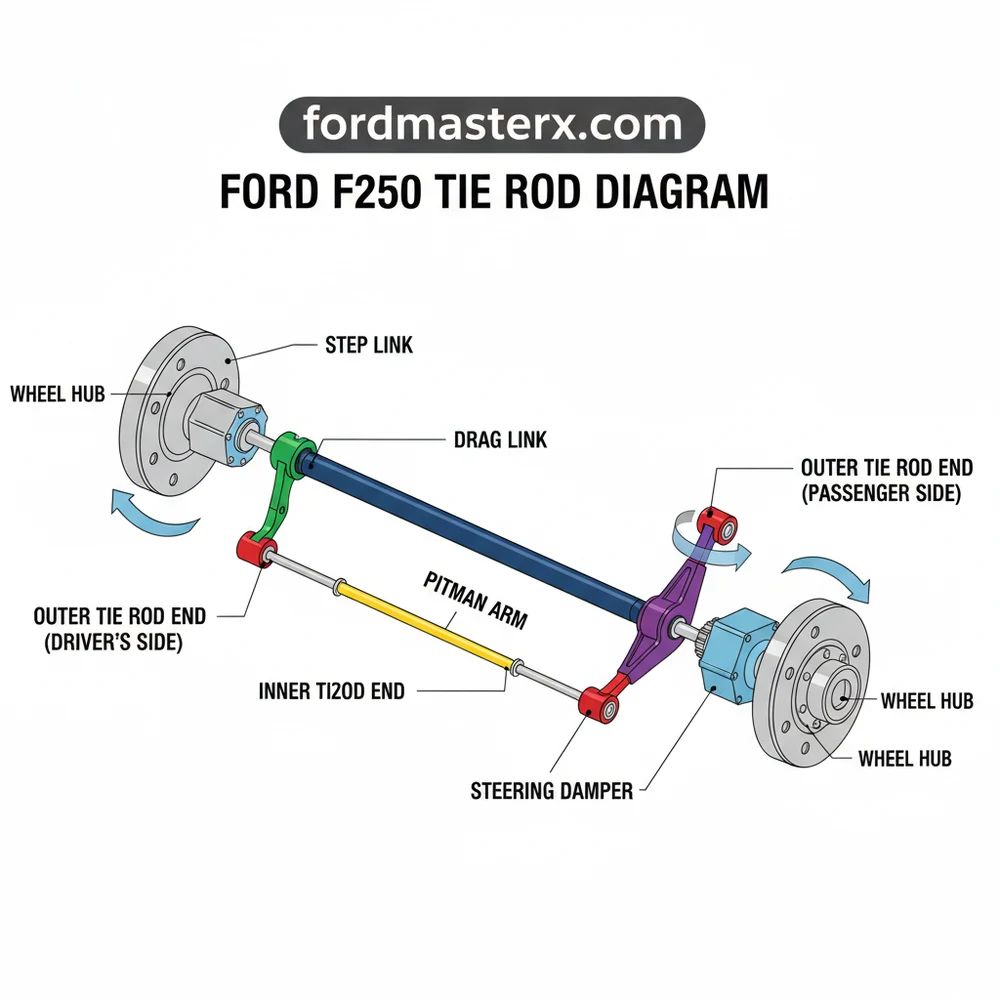
The diagram breaks down into several key components. First, you will see the outer tie rod ends, which connect directly to the steering knuckles at each wheel. These are the most common points of failure due to the constant pivoting they perform. Connecting these ends is the main tie rod tube or “center link.” In many configurations, an adjusting sleeve is present, allowing for precise toe-in and toe-out adjustments. This layout is vital for ensuring that both wheels turn in unison and maintain proper alignment during travel. Additionally, the Ford F250 tie rod diagram will often include the steering stabilizer (damper), which is bolted to the linkage to absorb vibrations and prevent “bump steer.”
Understanding how to read and interpret a Ford F250 tie rod diagram is the bridge between a theoretical repair and a successful one. Follow these steps to use the diagram for inspection or component replacement:
- ✓ Orient Yourself: Position yourself at the front of the truck looking toward the rear. Identify the driver’s side and passenger’s side components as mirrored in the layout.
- ✓ Locate the Drag Link: Find the rod that angles upward toward the driver’s side frame rail. This is the drag link, often confused with the main tie rod.
- ✓ Identify Adjusting Sleeves: Look for the threaded sections secured by two bolts. These are used to change the length of the rods without removing them.
- ✓ Check Ball Joint Integrity: Locate the rubber boots at the end of each rod. If the diagram shows a grease fitting (Zerk fitting), ensure yours are present and not damaged.
- ✓ Match the Blueprint to Reality: Use the schematic to count the number of components. If your truck has aftermarket “high-steer” kits, the layout may differ slightly from the OEM configuration.
When it comes time to replace a component identified in your Ford F250 tie rod diagram, preparation is paramount. You will need a specific set of tools, including a heavy-duty floor jack, jack stands rated for at least 3 tons, a large torque wrench (capable of reaching 100+ lb-ft), a pickle fork or tie rod end puller, and a set of deep-well sockets ranging from 18mm to 30mm.
Never work under a Ford F250 supported only by a hydraulic jack. These trucks are exceptionally heavy; always use high-capacity jack stands positioned on a level, concrete surface.
To begin a replacement, loosen the lug nuts on the front wheels before lifting the vehicle. Once the truck is securely on stands and the wheels are removed, use your Ford F250 tie rod diagram to locate the specific joint needing replacement. Remove the cotter pin from the castle nut and unscrew the nut partially. Using your puller tool, apply pressure until the tapered stud “pops” out of the knuckle. Before fully unscrewing the old tie rod end, count the number of visible threads or measure the distance from the center of the joint to a fixed point on the rod. This helps maintain a rough alignment so you can safely drive to an alignment shop afterward.
One of the most frequent reasons truck owners seek out a Ford F250 tie rod diagram is to diagnose the infamous “Death Wobble.” This is a violent shaking of the front end that usually occurs after hitting a bump at highway speeds. By referencing the schematic, you can systematically check each “pivot point” for play. If a tie rod end can be moved up and down by hand, or if the rubber boot is torn and leaking grease, it has failed.
Have an assistant sit in the cab and turn the steering wheel back and forth rapidly while you watch the linkage. Use the diagram to identify which joint is clicking or showing independent movement; that is your culprit.
Other common issues include uneven tire wear, specifically “cupping” or “feathering” on the outer edges, which indicates that the tie rods are no longer holding the wheels at the correct angle. If your steering wheel is off-center while driving straight, the drag link adjustment—clearly shown in the Ford F250 tie rod diagram—needs to be corrected. If you notice a “dead zone” in the steering where you can turn the wheel several inches before the truck responds, the inner or outer tie rod ends are likely excessively worn.
Maintaining your steering system is about more than just replacing broken parts; it is about preventative care. For Ford F250 owners, especially those who use their trucks for towing or off-roading, the steering linkage is under constant stress. We recommend greasing all Zerk fittings every time you change your oil. If your truck came with “sealed-for-life” factory joints, consider upgrading to greasable aftermarket components, which allow you to flush out contaminants and moisture.
When purchasing new parts, look for “heavy-duty” or “oversized” versions of the components found in your Ford F250 tie rod diagram. These often feature larger ball studs and thicker wall tubing to resist bending. Additionally, after any work is performed on the steering linkage, a professional four-wheel alignment is mandatory. Even if you measured the threads perfectly, a fraction of an inch of misalignment can ruin a set of expensive tires in less than a thousand miles.
In conclusion, utilizing a Ford F250 tie rod diagram is the most effective way to ensure your truck remains safe and predictable on the road. By understanding the structure and layout of your steering system, you can save money on diagnostic fees and gain the confidence to perform your own repairs. Keep your schematic handy, use quality components, and never ignore the early warning signs of steering wear. Proper maintenance of your tie rod system ensures that your Ford F250 continues to provide the rugged reliability it was built for.
Step-by-Step Guide to Understanding the Ford F250 Tie Rod Diagram: Component Layout Guide
Identify the components using the Ford F250 tie rod diagram to distinguish between inner and outer ends.
Locate the adjusting sleeves and tie rod ends within the front suspension layout to assess their condition.
Understand how the steering system transfers force through the linkage by tracing the connection points shown.
Apply the diagram’s configuration to ensure new parts are oriented correctly during the assembly process.
Verify that all castle nuts are tightened to spec and secured with new cotter pins for safety.
Complete the process by scheduling a professional alignment to finalize the steering system geometry.
Frequently Asked Questions
Where is the tie rod located?
Tie rod ends are located at the ends of the steering linkage, connecting the drag link or center link to the steering knuckles on both front wheels. They sit behind the wheel assembly and are easily visible once the vehicle is lifted or the wheels are turned fully to one side.
What does this diagram show?
The ford f250 tie rod diagram shows the complete steering linkage system, including the inner and outer tie rod ends, adjusting sleeves, and the drag link. It clarifies how these parts interact to transfer steering wheel movement to the front wheels for precise directional control.
How many connections does the system have?
The steering configuration typically features two outer tie rod ends and two inner tie rod ends or a drag link assembly. These components connect via threaded adjusting sleeves, which allow for fine-tuning the toe alignment, ensuring the wheels remain parallel while driving straight ahead.
What are the symptoms of a bad tie rod?
Symptoms of a failing tie rod include a vibrating steering wheel, clunking noises when turning, and uneven tire wear. You may also notice the vehicle wandering or pulling to one side, indicating that the steering component structure has become loose or damaged and requires immediate attention.
Can I replace this myself?
Replacing tie rods is a common DIY task for those with basic mechanical knowledge. However, because it directly affects the vehicle’s steering system and alignment, you must have the front end professionally aligned immediately after the installation to prevent rapid tire wear and ensure safe handling.
What tools do I need for this task?
To service the tie rod assembly, you will need a floor jack, jack stands, a socket set, a torque wrench, and a tie rod end puller or pickle fork. A measuring tape is also helpful for maintaining a rough alignment until you reach a professional alignment shop.


