Ford F250 Front Axle Parts Diagram: Complete Guide
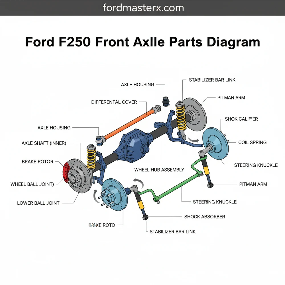
This Ford F250 front axle parts diagram illustrates the complex assembly of the 4WD system, including the differential, axle shafts, and steering knuckles. It provides a visual layout of every internal and external component, allowing owners to pinpoint specific parts for maintenance, upgrades, or critical front-end repairs.
📌 Key Takeaways
- The diagram serves to visualize the intricate axle structure and part relationships.
- Identifying the differential housing and axle seals is critical for leak prevention.
- Always use heavy-duty jack stands to secure the vehicle before performing axle work.
- Cross-reference diagram part numbers with your specific axle model (Dana 50 or Dana 60).
- Use this diagram when replacing U-joints, ball joints, or troubleshooting 4WD issues.
When you are faced with a complex repair or routine maintenance on a heavy-duty truck, having access to an accurate ford f250 front axle parts diagram is the difference between a successful afternoon in the garage and a week of frustration. The front axle of a Ford F250 is a sophisticated piece of engineering designed to handle immense torque and heavy payloads, making it significantly more complex than a standard passenger vehicle. By utilizing a high-quality schematic, you gain a clear visual roadmap that identifies every bolt, seal, and gear within the assembly. This article provides a comprehensive overview of the front axle configuration, teaching you how to interpret technical blueprints and apply that knowledge to real-world troubleshooting and component replacement, ensuring your Super Duty remains roadworthy and reliable.
Most Ford F250 models utilize a Dana 60 or a variation known as the “Super 60” front axle. These are non-independent, solid-beam axles (Mono-beam) that rely on a central differential housing and stout steering knuckles to provide both power and directional control.
The internal structure of the Ford F250 front axle system is composed of several critical sub-assemblies that work in unison. At the heart of the system is the differential carrier, often referred to as the pumpkin. This housing contains the ring and pinion gears, which translate the rotation of the driveshaft to the lateral axle shafts. A standard ford f250 front axle parts diagram will illustrate the layout of the inner axle shafts extending from the differential toward the wheel ends. These shafts are connected to the outer stub shafts via universal joints (U-joints), which allow the wheels to turn while still receiving power.
Surrounding these moving parts is the structural housing, which includes the axle tubes and the steering knuckles. The knuckles are attached to the axle “C” brackets via upper and lower ball joints, providing the pivot points for steering. One of the most important aspects of the schematic is the hub assembly. On the F250, this typically includes the wheel bearings, the vacuum-operated or manual locking hub mechanism, and the ABS speed sensor. The diagram will also detail the various seals—such as the inner axle seal and the outer dust seal—which are crucial for keeping gear oil inside the housing and contaminants like mud and water out. Depending on whether your truck features the Electronic Locking Differential (ELD) or a standard open carrier, the internal configuration of the differential may show slight variations in wiring and actuator placement.
[DIAGRAM_PLACEHOLDER – A detailed technical schematic showing the Dana 60 front axle assembly, exploded view, including differential gears, axle shafts, U-joints, knuckles, and locking hub components with numerical callouts for each part.]
Interpreting a complex blueprint requires a systematic approach. When you look at a ford f250 front axle parts diagram, you are seeing an “exploded view,” where parts are pulled away from their seated positions to show how they fit together. To use this information effectively for an installation or repair, follow this step-by-step guide to understanding and working with the system.
- ✓ Identify the Primary Axis: Locate the centerline of the axle in the diagram. This helps you distinguish between the “long side” (usually the passenger side) and the “short side” (driver side) axle shafts.
- ✓ Cross-Reference Part Numbers: Most diagrams include a legend or index. Use the numerical callouts to find the exact Ford OEM part number, which is essential for ensuring compatibility with your specific trim and gear ratio.
- ✓ Analyze the Seal Stack: Pay close attention to the order of seals and washers near the wheel hub. Installing a vacuum seal or a thrust washer in the wrong orientation is a common mistake that leads to 4×4 engagement failure.
- ✓ Gather Necessary Tools: Based on the hardware shown in the schematic, you will likely need a 13mm 12-point socket for the hub bolts, a 30mm or larger socket for the axle nut, a heavy-duty ball joint press, and a torque wrench capable of reaching at least 150 lb-ft.
- ✓ Prepare for Disassembly: Start from the outside and work in. Remove the brake caliper and rotor first, then the locking hub, followed by the hub bearing assembly. The diagram will show the hidden bolts behind the knuckle that must be accessed.
- ✓ Inspect for Wear: As you remove each component shown in the layout, compare its condition to the “perfect” version in the drawing. Look for pitting on the U-joint caps or metal shavings in the differential fluid.
- ✓ Reinstall with Precision: Use the diagram as a checklist to ensure no shims or spacers are left on the workbench. Apply the specified grease to the needle bearings and spline surfaces as indicated by the lubrication points in the manual.
Always support the vehicle with heavy-duty jack stands rated for the F250’s weight. Never work under a truck supported only by a floor jack. Additionally, be cautious when removing the coil springs if your project involves the axle housing itself, as they are under immense tension.
Even the most robust trucks encounter issues, and the F250 is no exception. Common problems include the “Death Wobble,” which is often caused by worn ball joints or a failing track bar bushing. By consulting the ford f250 front axle parts diagram, you can pinpoint these pivot points and check for play. Another frequent issue is the failure of the Pulse Vacuum Hub (PVH) system. If your 4×4 won’t engage, the schematic helps you trace the vacuum lines from the knuckle back to the solenoid, identifying potential leak points at the main hub seal.
Leaking differential fluid is another sign of trouble, usually originating from the inner axle seals or the pinion seal. The diagram illustrates how these seals are seated deep within the axle tubes, indicating that a full teardown of the carrier may be required for replacement. If you hear a rhythmic clicking while turning, the U-joints at the steering knuckles are likely the culprit. Utilizing the diagram helps you visualize how the axle shaft must be pulled through the knuckle to access these joints. If you notice uneven tire wear or “feathering,” use the overview of the steering linkage to inspect the tie rod ends and drag link for excessive movement.
When replacing hub bearings, always replace the yellow O-ring and the large metal-clad vacuum seal. Reusing these components is the leading cause of 4×4 engagement issues, as they lose their ability to hold a vacuum over time.
To maximize the lifespan of your front axle, regular maintenance is paramount. One of the best practices is to manually cycle your locking hubs at least once a month, even if you don’t need 4WD. This keeps the internal gears lubricated and prevents the dial from seizing due to corrosion. When referring to your ford f250 front axle parts diagram for maintenance, look for grease zerks. While many modern F250 components are “sealed for life,” many high-quality aftermarket replacements feature greaseable fittings that significantly extend the part’s service life if maintained every oil change.
Cost-saving advice for F250 owners often involves knowing when to buy assemblies versus individual components. For instance, if your wheel bearings are shot, it is often more cost-effective to buy the entire hub assembly rather than attempting to press out individual bearings, as the labor and specialized tools required often outweigh the savings. However, for the differential itself, always stick to high-quality OEM or reputable gear brands like Dana or Yukon. Using sub-par gears or bearings in a high-torque system like the F250’s can lead to catastrophic failure. Finally, always use the specific gear oil weight recommended in your owner’s manual—typically 75W-140 synthetic for the rear, but verify the front requirements as they can differ based on the axle configuration. Keeping a printed copy of the schematic in your truck’s glovebox can be an invaluable resource for emergency roadside repairs or for communicating clearly with a mechanic. Knowing your vehicle’s structure empowers you to make informed decisions about its care and longevity.
Step-by-Step Guide to Understanding the Ford F250 Front Axle Parts Diagram: Complete Guide
Identify the specific axle model on your Ford F250 by checking the ID tag located on the differential housing.
Locate the primary components on the diagram, such as the steering knuckle, hub assembly, and axle shafts.
Understand how the vacuum lines and locking hubs integrate into the overall 4WD system configuration and layout.
Connect the visual representation in the diagram to the physical parts on your vehicle to find worn components.
Verify that all replacement parts match the diagram’s specifications and dimensions before starting the installation process.
Complete the repair by reassembling the components in the reverse order indicated by the diagram’s organizational structure.
Frequently Asked Questions
Where is the axle shaft located?
The axle shaft is located inside the axle housing, extending from the differential to the wheel hubs. On an F250, the front axle system features both inner and outer shafts connected by a U-joint, allowing the wheels to receive power while maintaining steering capabilities during operation.
What does this diagram show?
This diagram shows the complete internal and external configuration of the front axle assembly. It highlights the relationship between the differential gears, bearings, seals, and the steering knuckle, providing a clear map for anyone performing a total rebuild or simple component replacement on their truck.
How many seals does the front axle have?
A standard F250 front axle configuration typically includes two inner axle seals near the differential and two outer dust seals or vacuum seals at the wheel hubs. These components are vital for maintaining lubrication within the axle structure and preventing debris from entering the internal gear system.
What are the symptoms of a bad front axle?
Common symptoms include clunking sounds when turning, excessive vibration at high speeds, or visible grease leaking from the axle seals. If the 4WD system fails to engage, the diagram can help locate the vacuum lines or locking hub components that may be faulty within the system.
Can I replace front axle parts myself?
You can replace many external components like hubs and U-joints with basic mechanical knowledge and heavy-duty tools. However, rebuilding the internal differential or replacing inner seals often requires specialized equipment and precise measurements to ensure the axle structure remains properly aligned and fully functional for driving.
What tools do I need for axle repair?
Essential tools include a heavy-duty floor jack, jack stands, a torque wrench, and a socket set. For deeper repairs, you may need a ball joint press, a seal driver, and snap ring pliers to navigate the specific layout of the Ford F250 front axle assembly.


