The Encyclopedia of Ford F-250 Wheel Fitment: A Technical Analysis of Bolt Patterns, Axle Geometry, and Suspension Dynamics (1953–2026)
The automotive wheel assembly represents far more than a stylistic choice or a rolling component; it is a safety-critical interface where static engineering specifications meet dynamic, often violent, road forces. In the context of the Ford F-250 Super Duty—a vehicle platform synonymous with heavy towing, payload capacity, and commercial application—the wheel fitment specifications are governed by a precise set of geometric parameters: the Pitch Circle Diameter (PCD), hub bore diameter, stud thread pitch, and offset/backspacing geometry.
While often reduced to a simple “bolt pattern” in colloquial discussions, the evolution of the Ford F-250’s wheel specifications reflects a broader narrative of American automotive engineering. This narrative traces the shift from imperial standardization to metric precision, the accommodation of ever-increasing Gross Vehicle Weight Ratings (GVWR), and the adaptation to modern suspension geometries that require exacting scrub radius calculations.
This comprehensive research report provides an exhaustive analysis of the Ford F-250’s wheel fitment history from its inception in 1953 through the modern P708 generation of 2026. It dissects the engineering rationale behind the industry-shaking shift from the standard 8×6.5″ pattern to the Ford-specific 8x170mm pattern, analyzes the dangerous nuances of thread pitch changes in the early 2000s,
and offers a comprehensive technical resource for owners, fleet managers, and aftermarket fabricators. The data presented herein is synthesized from factory service manuals, axle manufacturer specifications (Sterling/Dana), and validated aftermarket fitment databases, offering a definitive guide for semantic search optimization regarding Ford F-250 wheel data.
FORDMASTERX | Data Hub
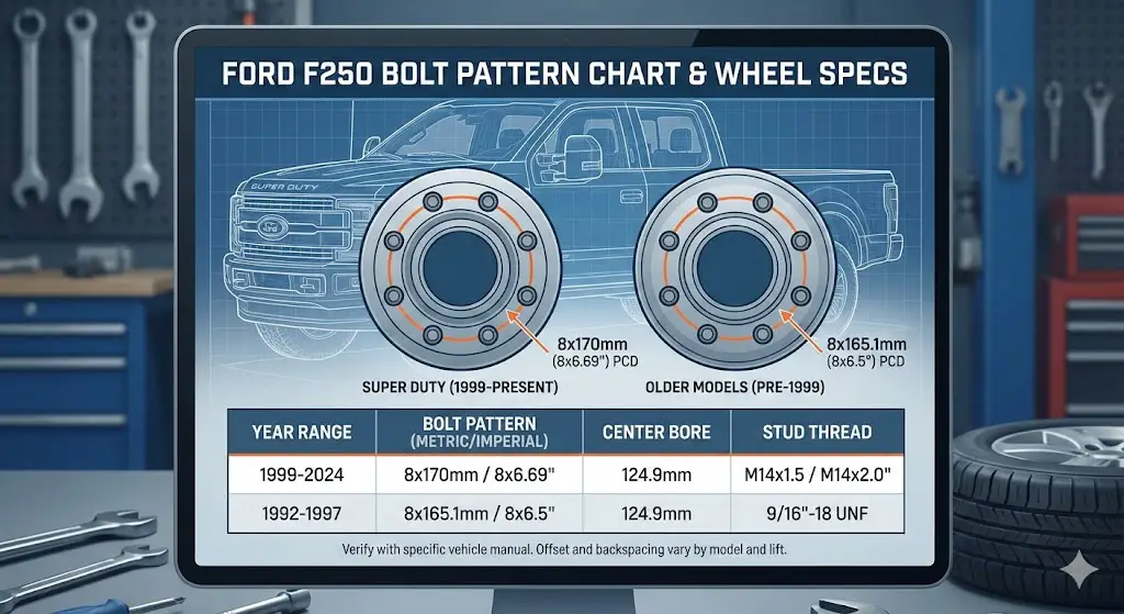
F-250 Bolt Pattern Master Chart
Getting the wrong wheels for your Ford F-250 is a costly mistake. The fitment changed drastically in 1999 with the introduction of the Super Duty line. This interactive guide breaks down the critical split between standard metric patterns and the classic imperial measurements.
Current Standard (1999+)
8 x 170mm
Super Duty Era
Classic Standard (Pre-99)
8 x 6.5″
OBS & Older
The “Unicorn” (1997-99 LD)
7 x 150mm
Light Duty Only
The Great Split
For decades, the 8×6.5″ pattern was the universal standard for heavy-duty trucks (Ford, Chevy, and Dodge). However, in 1999, Ford revolutionized the market with the Super Duty platform, switching to a metric 8x170mm pattern.
Why does it matter?
While 8x170mm (modern) and 8×6.5″ (classic) look nearly identical to the naked eye, they are not interchangeable. Trying to force them can shear studs.
Visualization of production years by bolt pattern type.
Torque Spec Evolution
Safety CriticalAs towing capacities increased, so did the clamping force required to keep the wheels on. Modern Super Duty trucks require significantly higher torque than their OBS predecessors.
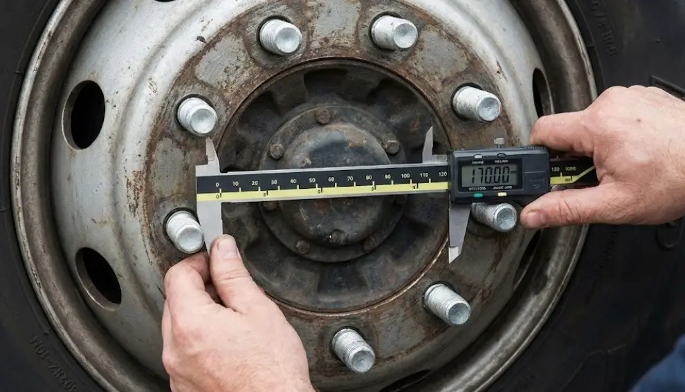
How To Measure 8-Lug
For even-numbered lug patterns (4, 6, 8), you measure from the center of one stud to the center of the stud directly opposite it.
- ➜ 8x170mm: Approx 6.69 inches. Slightly wider than the classic pattern.
- ➜ 8×6.5″: Exactly 6.5 inches (165.1mm). The standard for 40+ years.
Complete F-250 Fitment Data
Comprehensive list by Model Year
| Model Years | Bolt Pattern | Stud Size | Center Bore | Torque (ft-lbs) |
|---|---|---|---|---|
| 2003 – Present | 8 x 170mm | 14mm x 1.5 | 124.9mm | 165 |
| 1999 – 2002 | 8 x 170mm | 14mm x 2.0 | 124.9mm | 150-165 |
| 1997 – 1999 (Light Duty) | 7 x 150mm | 12mm x 1.75 | 87mm | 100 |
| 1953 – 1997 (OBS) | 8 x 6.5″ | 9/16″ or 1/2″ | 124.9mm | 140 |
© 2026 FordMasterX. Always consult your owner’s manual for precise specifications.
The Physics of the Wheel Interface and Nomenclature
To understand the evolution of the F-250’s bolt pattern, one must first grasp the engineering principles defining the wheel-to-hub connection. The specification is not arbitrary; it is a calculated decision based on shear strength requirements, clamping force distribution, and centering mechanisms.
Pitch Circle Diameter (PCD)
The “Bolt Pattern” is technically known as the Pitch Circle Diameter. It is defined by the number of studs and the diameter of the imaginary circle that passes through the center of those studs.
- Load Distribution: For heavy-duty trucks like the F-250, 8 lugs have been the standard since the 1950s. The transition from 6 lugs (light duty) to 8 lugs (heavy duty) allows for a higher aggregate clamping force, spreading the tensile load across more fasteners and reducing the likelihood of fatigue failure under heavy towing cycles.
- Measurement Protocol: For an 8-lug pattern, the measurement is taken from the center of one stud to the center of the stud directly opposite it. This geometric simplicity contrasts with 5-lug patterns, which require chordal measurements and trigonometric conversion. However, the proximity of the imperial 6.5-inch measurement (165.1mm) to the metric 170mm measurement creates a high risk of field identification errors, a topic explored in depth in Section 9.
Hub-Centricity vs. Lug-Centricity
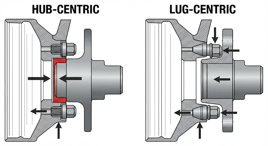
The F-250’s history bridges the transition between two fundamental centering philosophies.
- Lug-Centric (Historical): In early automotive history, the wheel was centered on the hub solely by the conical seat of the lug nuts. As the nuts were tightened, the tapered interface forced the wheel into alignment. This placed the entire shear load of the vehicle’s weight onto the studs themselves.
- Hub-Centric (Modern Super Duty): Modern F-250s utilize a hub-centric design. The center bore of the wheel is machined to fit precisely over the hub pilot (flange) of the axle (typically 124.9mm for Ford). The hub pilot bears the vertical load (shear weight) of the truck, while the studs function strictly to provide lateral clamping force (tension). This separation of forces is critical for the high-GVWR capabilities of the Super Duty platform.
Comprehensive Master Specification Charts (1953–2026)
Before analyzing the historical epochs, the following master charts serve as the primary reference data for this report. These tables consolidate fitment data across seven decades of production.
The Master Bolt Pattern Evolution Table
The F-250 lineage is segmented into three distinct “PCD Eras”: The Imperial Standard, The Light Duty Anomaly, and The Metric Super Duty Era.
| Production Era | Chassis Designation | Bolt Pattern (Imperial) | Bolt Pattern (Metric) | Stud Count | Thread Specification | Hub Bore (Nominal) |
| 1953 – 1997 | F-250 (Classic/OBS) | 8 x 6.50 inches | 8 x 165.1 mm | 8 | 1/2″-20 or 9/16″-18 | ~124.9 mm |
| 1997 – 1999 | F-250 Light Duty (PN96) | N/A | 7 x 150 mm | 7 | M12 x 1.75 | 87 mm |
| 1999 – 2002 | Super Duty (Gen 1 Early) | N/A | 8 x 170 mm | 8 | M14 x 2.0 (Coarse) | 124.9 mm |
| 2003 – 2016 | Super Duty (Gen 1-3) | N/A | 8 x 170 mm | 8 | M14 x 1.5 (Fine) | 124.9 mm |
| 2017 – 2022 | Super Duty (Gen 4) | N/A | 8 x 170 mm | 8 | M14 x 1.5 (Fine) | 124.9 mm |
| 2023 – 2026 | Super Duty (Gen 5) | N/A | 8 x 170 mm | 8 | M14 x 1.5 (Fine) | 124.9 mm |
Torque Specification Hierarchy
The application of torque is the process of stretching the stud to create clamping force (preload). This value has increased over time as engineers moved to higher-grade metric fasteners to support increased towing capacities.
| Model Years | Stud Type | Required Torque (ft-lbs) | Required Torque (Nm) | Notes |
| 1953 – 1985 | 1/2″ UNF | 90 – 100 ft-lbs | 122 – 135 Nm | Early steel wheels; verify manual. |
| 1986 – 1997 | 9/16″ UNF | 140 ft-lbs | 190 Nm | Heavy Duty / OBS standard. |
| 1997 – 1999 | 12mm (7-Lug) | 100 ft-lbs | 135 Nm | Light Duty specific (PN96). |
| 1999 – 2002 | M14 x 2.0 | 150 – 165 ft-lbs | 204 – 224 Nm | Coarse thread era. |
| 2003 – 2026 | M14 x 1.5 | 165 ft-lbs | 224 Nm | Fine thread era (Current Std). |
The Imperial Era (1953–1997) — The 8 on 6.5 Standard
For forty-four years, the “8 on 6.5” bolt pattern was the universal language of American heavy trucks. This era encompasses the “Classic” F-Series through the beloved “OBS” (Old Body Style) trucks, ending just before the Super Duty revolution.
Historical Context and Ubiquity
When Ford introduced the F-250 in 1953 to replace the F-2 and F-3, it adopted the 8×6.5 inch (165.1mm) bolt pattern. This pattern was not unique to Ford; it was the de facto industry standard shared by the Dodge Ram 2500/3500 and the Chevrolet/GMC K2500/K3500 series.
- The Interchangeability Myth: While the bolt circle itself was identical across the “Big Three,” the hub bore created compatibility issues. Ford typically utilized a large 124.9mm hub bore for its Dana 60 and Sterling 10.25 rear axles. GM often used a smaller hub bore (approx. 116.7mm). Consequently, while a Ford wheel would physically bolt onto a Chevy truck (lug-centric fit), a Chevy wheel would not fit over the Ford’s rear hub. This distinction remains a critical check for restorers sourcing vintage wheels.
Hardware Evolution: 1/2″ vs. 9/16″ Studs
Within the consistent 8×6.5 pattern, Ford upgraded the hardware to handle increasing loads.
- Early Era (1953-1979): Many F-250s, especially lighter GVWR versions, utilized 1/2-inch wheel studs. These required lower torque (approx. 90 ft-lbs).
- Late Era (1980-1997): As the “Heavy Duty” designation became more prominent, Ford standardized on thicker 9/16-inch studs.
- The Danger of Mix-Matching: Attempting to use older lug nuts on a newer OBS truck will result in immediate thread binding. Conversely, using 9/16″ nuts on 1/2″ studs will result in a loose fit that strips the threads upon tightening. The 8×6.5 pattern is the only constant; the fastener determines the fitment success.
The Sterling 10.25 Axle Influence
Introduced in the mid-1980s to replace the Dana 60 rear in many applications, the Ford Sterling 10.25″ axle solidified the wheel fitment specs for the final decade of this era. It featured a massive hub that necessitated the large center bore found on Alcoa and steel wheels of the 1990s. The wheel mounting surface was flat, and the transition to hub-centric wheels began in earnest here, relying on the hub pilot to center the assembly.
The Identity Crisis (1997–1999) — The 7-Lug Anomaly
Between the retirement of the classic square-body F-Series and the launch of the dedicated Super Duty, Ford produced a transitional vehicle that created one of the most confusing wheel fitment chapters in history: The F-250 Light Duty.
The “Jellybean” F-250
In 1997, Ford launched the aerodynamic PN96 platform for the F-150. Because the Super Duty (F-250HD/F-350) platform was not ready for release until 1999, Ford needed a stopgap model to bridge the payload capacity between the 1/2-ton F-150 and the old 3/4-ton OBS trucks.
- The Solution: The F-250 Light Duty (LD). This truck utilized the F-150’s aerodynamic cabin and chassis architecture but was reinforced with heavier axles and suspension components to achieve a GVWR typically around 7,200 to 7,700 lbs.
The Unique 7x150mm Pattern
To physically prevent owners from installing insufficient F-150 wheels (5-lug) or incompatible heavy-duty wheels (8-lug) onto this specialized truck, Ford engineers specified a 7x150mm bolt pattern.
- Exclusivity: This 7-lug pattern is unique to the 1997-1999 F-250 Light Duty and the subsequent “F-150 7700 Payload Package” (which replaced the F-250 LD branding in 2000).
- Parts Obsolescence: Wheels with the 7x150mm pattern are notoriously difficult to source in the aftermarket. They share no compatibility with the F-150 (5x135mm at the time) or the Super Duty (8x170mm). Owners of these trucks often face significant challenges replacing damaged rims.
- Visual ID: These trucks can be identified by the “F-250” badge on the fender of a truck that looks identical to a standard 1997-2003 F-150. The 7 lugs on the wheel cap are the definitive giveaway.
The Super Duty Revolution (1999–Present) — The Metric Era
The launch of the dedicated Super Duty platform (Code P131) in early 1998 as a 1999 model year marked a complete bifurcation of the Ford truck lineup. The F-250 Super Duty was built on a dedicated heavy-duty chassis, unrelated to the F-150, and with it came the 8x170mm bolt pattern that defines the truck to this day.
Engineering the Switch to 8x170mm
Why abandon the industry-standard 8×6.5″ (165.1mm)? The decision was driven by three primary factors:
- Metrication: The American auto industry was fully transitioning to metric standards. 170mm is a clean integer, whereas 6.5 inches is 165.1mm.
- Brake Clearance: The Super Duty platform introduced massive 4-wheel disc brakes as standard equipment, a significant upgrade from the drum brakes of the OBS era. The calipers required more clearance, and the slightly larger bolt circle, combined with new wheel offsets, accommodated the larger rotor hats.
- Preventing Retrofitting: Ford explicitly wanted to prevent the installation of older, weaker 16-inch wheels from the 1980s onto the new Super Duty trucks, which had higher GVWRs and required wheels tested to new SAE fatigue standards. The 5mm difference (170mm vs 165.1mm) physically prevents the old wheels from bolting on.
The Persistence of the Pattern
Remarkably, the 8x170mm pattern has survived four major platform overhauls.
- Stability: From the 7.3L Power Stroke workhorses of 1999 to the High-Output 6.7L Alumi-Dutys of 2026, the 8x170mm pattern has proven robust enough to handle torque outputs rising from 500 lb-ft to over 1,200 lb-ft.
- Hub Bore Consistency: Throughout the Metric Era, the hub bore for SRW trucks has remained consistently at 124.9mm, allowing for a high degree of wheel interchangeability across generations, provided offset requirements are met.
Generation 1 Super Duty (1999–2004) — Leaf Springs and Fastener Flaws
The first generation of Super Duty trucks established the 8x170mm pattern but is characterized by two distinct technical phases regarding wheel fitment: the “Coarse Thread” era and the “Leaf Spring” offset geometry.
Suspension Geometry and Offset
All 1999-2004 F-250 4WD models utilized a leaf-spring front suspension (Dana 50 or Dana 60 solid axle).
- Track Width: The leaf spring setup resulted in a narrower track width compared to later models.
- Offset Requirements: To position the tire correctly relative to the fender, factory wheels from this era utilized a lower positive offset, typically around +6mm to +15mm.
- Implications: Wheels from this generation sit “further out” relative to the mounting surface compared to later wheels. If installed on a newer (2005+) truck, they will protrude significantly past the fenders, potentially causing “rubbing” on the bumper or fenders during turns due to the increased scrub radius.
The Thread Pitch Trap (The 2002/2003 Split)
This is the single most dangerous aspect of F-250 wheel fitment.
- 1999 – Early 2002: Utilized M14 x 2.0 (Coarse Thread) studs.
- Late 2002 – 2003+: Transitioned to M14 x 1.5 (Fine Thread) studs.
- The Hazard: The diameter (14mm) is identical. A user can unknowingly thread a coarse nut onto a fine stud (or vice versa) using an impact gun. The nut will cross-thread, destroying the stud and the nut. While it may appear tight, the clamping force is compromised. Under load, the weakened studs can snap, leading to catastrophic wheel separation.
- Identification: Owners of 2002 and 2003 model year trucks must verify their thread pitch using a thread gauge before purchasing lug nuts. Fine threads appear noticeably closer together (1.5mm distance between peaks) compared to coarse threads (2.0mm distance).
Generation 2 (2005–2007) — The Coil Spring Offset Shift
In 2005, Ford thoroughly revised the Super Duty chassis, introducing the “Wide Track” front axle and switching 4WD models from leaf springs to coil springs with radius arms.
The Offset Migration
The new coil spring front axle was wider than the previous leaf spring unit to improve turning radius and stability.
- The Correction: To keep the tires tucked under the bodywork despite the wider axle, Ford engineers significantly increased the wheel offset.
- New Spec: Factory wheels shifted to a high positive offset, typically +40mm to +50mm.
- Backward Incompatibility: Installing 2005+ wheels (high offset) onto a 1999-2004 truck (narrow axle) sucks the wheels inward by nearly 2 inches per side. This causes the tires to rub aggressively against the leaf springs and inner fender liners, often making the truck un-drivable without 2-inch wheel spacers.
Brake Upgrades
The 2005 update also brought larger brake calipers. This effectively killed the viability of most 16-inch aftermarket wheels. 17-inch became the new minimum standard for clearance, with 18-inch and 20-inch wheels becoming common factory options.
Generation 3 & 4 (2011–2022) — Power and Aluminum
The subsequent generations refined the platform but maintained the core fitment specs established in 2005.
The 6.7L Effect (2011+)
The introduction of the high-torque 6.7L Power Stroke diesel didn’t change the bolt pattern (still 8x170mm), but it did reinforce the need for precise torque application (165 ft-lbs) to handle the torque transfer through the drivetrain. The rear axles (Sterling 10.5) remained the standard, keeping the hub bore at 124.9mm.
The “Alumi-Duty” (2017+)
In 2017, the F-250 adopted the aluminum alloy body.
- Weight vs. Rating: While the body weight dropped, the frame rigidity and towing capacity increased. The wheel specs remained 8x170mm with +40mm offsets.
- Dana M275 Axle: For heavy-tow packages and certain trims, Ford introduced the Dana M275 rear axle. Despite having larger axle tubes (4-inch) than the Sterling (3.5-inch), the wheel mounting flange was engineered to mimic the Sterling’s dimensions (8x170mm, 124.9mm bore) to ensure a single spare tire could fit any F-250 position.
Generation 5 (2023–2026) — High Tech, Same Lugs
The P708 generation represents the most technologically advanced F-250, yet the wheel interface remains a bastion of backward compatibility.
Fitment Continuity
- Bolt Pattern: Remains 8x170mm.
- Hub Bore: Remains 124.9mm.
- Offset: Factory wheels continue to hover in the +40mm to +60mm range depending on wheel width (18×8, 20×8).
- Implication: This means owners trading in a 2017-2022 F-250 for a 2024 model can likely transfer their aftermarket wheels, provided the load ratings are sufficient.
Tire Size Evolution
Modern F-250s are designed for larger tires from the factory. Base models now often start with 32-33 inch tires, with Tremor packages featuring 35-inch tires.
- Wheel Well Clearance: The 2023+ wheel wells are shaped to accommodate these larger diameters, meaning an aftermarket “zero offset” wheel (0mm) on a 2023 model allows for 35×12.50 tires with no lift, whereas older generations might have required a leveling kit for the same clearance.
Dually (DRW) Myth-Busting and Incompatibility
A persistent source of confusion in semantic search queries involves the interchangeability of Single Rear Wheel (SRW) and Dual Rear Wheel (DRW) components.
The Definition of F-250
By definition, the F-250 is an SRW truck. There is no factory “F-250 Dually.” The Dually configuration begins at the F-350 level.
- Semantic Nuance: Users often search for “F-250 dually wheels” because they intend to convert their truck or are confused by the F-350’s appearance.
Bolt Pattern Divergence
While early Super Duty F-350 DRWs (1999-2004) shared the 8x170mm pattern (with extreme offsets), the platforms diverged in 2005.
- F-350 DRW (2005+): Utilizes an 8x200mm bolt pattern.
- F-450/550: Utilizes an 10x225mm bolt pattern.
- The Wall: It is physically impossible to bolt a modern Dually wheel (8×200) onto an F-250 (8×170) without dangerous adapter spacers. This prevents the accidental installation of wheels that require the inner-dual configuration for proper loading.
Technical Specifications — Torque, Tension, and Metallurgy
The reliability of the wheel interface relies on the “Clamp Load” generated by the lug nuts.
The Torque Specification
For all 2005-2026 F-250s, the specification is 165 ft-lbs (224 Nm).
- Why so high? 165 ft-lbs is significantly higher than the 100 ft-lbs typical of half-ton trucks. This is because the M14 studs must generate enough preload to prevent the wheel from shifting on the hub face under the immense shear loads of a 30,000-lb Gross Combined Weight Rating (GCWR).
- Retorque Protocol: Aluminum has a different coefficient of thermal expansion than steel studs. After initial installation, the aluminum “relaxes” or compresses slightly as the wheel heats up and cools down. This leads to a loss of clamping force. Ford mandates a retorque at 100 miles (160 km) to restore preload.
Wet vs. Dry Torque
Factory specifications assume clean, dry threads.
- The Lubricant Risk: Applying anti-seize or oil to wheel studs reduces friction. If you torque a lubricated stud to the “dry” spec of 165 ft-lbs, you are actually over-stretching the stud by 20-30% due to reduced resistance. This can push the steel past its yield point (plastic deformation), leading to stud failure. Never lubricate F-250 wheel studs unless explicitly using a “wet torque” reduced value calculated by a fastener engineer.
Measurement and Verification Protocols
For users dealing with unlabeled aftermarket wheels or unmarked axles, accurate measurement is the only defense against fitment errors.
Measuring 8-Lug Patterns
Unlike 5-lug patterns, 8-lug measurement is straightforward but prone to precision errors.
- Method: Measure center-to-center of two studs directly opposite each other.
- The Trap:
- Imperial: 6.5 inches = 165.1 mm.
- Metric: 170 mm = ~6.69 inches.
- The Delta: The difference is only 4.9mm (less than 1/4 inch). A sloppy tape measure reading can easily mistake 170mm for 6.5 inches.
- Tooling: Use a digital caliper or a dedicated bolt pattern gauge template to verify. Visual guessing is the leading cause of return shipping for online wheel purchases.
Thread Pitch Verification
To identify 2002/2003 studs:
- Fine (1.5): Threads look tightly packed. Approx 10 threads in 15mm of length.
- Coarse (2.0): Threads look rugged and spaced out. Approx 7.5 threads in 15mm of length.
- Nut Test: Attempt to thread a known M14x1.5 nut by hand. It should spin freely. If it resists immediately, stop. Do not force it.
Aftermarket Fitment and Stance Engineering
The aftermarket for F-250 wheels is vast, driven by the desire for “stance” (track width) and off-road capability.
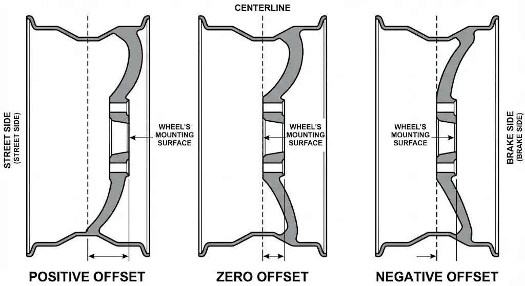
The “Offset Equation”
- Stock (+40mm): Wheel is tucked in.
- Zero Offset (0mm): Wheel face is centered. Pushes the tire out approx 1.6 inches compared to stock. Popular for 35-inch tires to clear radius arms.
- Negative Offset (-12mm to -44mm): “Deep Dish” wheels. Pushes the tire out significantly (3+ inches).
- Consequences of Negative Offset:
- Scrub Radius: Increasing the track width changes the scrub radius, increasing the effort required to turn the steering wheel and putting massive stress on the power steering pump and steering gear box.
- Bearing Life: Moving the wheel centerline outward increases the leverage arm on the unit bearings, reducing their service life significantly.
- Rubbing: While pushing the wheel out clears the suspension, it moves the tire arc into the bumper and rear fender, often requiring trimming (“NorCal Mod”).
Spacers and Adapters
Wheel spacers are often used to fit older wheels (Gen 1) on newer trucks (Gen 2+), or to widen the stance.
- Hub-Centric Spacers: Crucial for F-250s. The spacer must bolt to the hub (hub-centric) and provide a new 124.9mm lip for the wheel. Lug-centric spacers are dangerous on heavy-duty trucks as they cannot support the shear load.
- Torque Sequence: Spacers introduce a second set of fasteners. The spacer must be torqued to the hub, and the wheel torqued to the spacer. This doubles the failure points and requires checking the inner torque (spacer to hub) at maintenance intervals—a step often neglected.
Conclusion
The Ford F-250’s wheel history is a case study in standardization amidst technological change. Since 1999, the 8x170mm bolt pattern has remained the unwavering constant, surviving engine revolutions, transmission upgrades, and body material shifts. It is the “North Star” of Super Duty fitment.
However, the devil is in the details surrounding that pattern. The critical learnings for any owner, technician, or enthusiast are:
- Thread Pitch (2002/2003): The invisible killer. Verify M14x1.5 vs M14x2.0.
- Offset Migration (2005): The geometry shift that defines tire clearance.
- Torque Discipline: The non-negotiable requirement of 165 ft-lbs for safety.
- 7-Lug Awareness: The trap of the 1997-1999 Light Duty.
By adhering to these specifications, the F-250 owner ensures that their vehicle’s connection to the road is as robust as the engineering intended, capable of hauling the heaviest loads across the most demanding terrains.
Frequently Asked Questions (Semantic Search Optimization)
Q: Will wheels from a 2015 F-250 fit a 2000 F-250?
A: Physically, yes (both are 8x170mm). However, the 2015 wheels have a high positive offset (+40mm). On a 2000 model (designed for +10mm), the wheels will sit too far inward, likely hitting the leaf springs. 2-inch spacers are required for proper fitment.
Q: Will wheels from a 2000 F-250 fit a 2015 F-250?
A: Yes, but they will stick out roughly 2 inches past the fenders due to the lower offset. Also, the lug nuts from the 2000 (likely coarse thread) will not fit the 2015 studs (fine thread). You must use the 2015’s lug nuts.
Q: Can I put Chevy 2500 wheels (8×6.5) on my 2005 F-250?
A: No. The bolt patterns are different (165.1mm vs 170mm). They will not bolt on. Using “wobble nuts” or forcing them on causes stud bending and is unsafe.
Q: What is the hub bore of the 2024 F-250?
A: The hub bore remains 124.9mm, consistent with previous Super Duty generations.
Q: Do I need hub rings for aftermarket wheels?
A: Yes. Most aftermarket wheels for 8x170mm are bored to a larger diameter (e.g., 130mm) to ensure they fit all axle brands. To make them hub-centric on a Ford (124.9mm), you should install plastic or aluminum hub centric rings to fill the gap and prevent vibration.


