Ford F150 Fuse Box Diagram: Diagnosis & Fix Guide
The Ford F150 fuse box locations include the passenger compartment panel located under the dashboard to the left of the steering column and the power distribution box located in the engine compartment near the battery. These diagrams identify critical circuits for the ECU, fuel pump, and OBD-II diagnostic systems.
📌 Key Takeaways
- Identifies both the interior fuse panel and engine bay power distribution box layout
- Critical for locating the ECU fuse and OBD-II port power supply
- Always use the correct amperage rating to prevent electrical fires or harness damage
- A blown fuse is often the first thing to check when electronic components fail
- Essential for troubleshooting power loss before performing expensive parts replacement
When your truck experiences a sudden electrical failure, the 1997 ford f150 fuse box diagram becomes your most valuable diagnostic tool. Whether your windows refuse to roll down, your radio goes silent, or your engine cranks but won’t start, understanding the electrical architecture of this classic tenth-generation pickup is essential for any DIY repair. This guide provides a comprehensive breakdown of both fuse locations, explains how to interpret the complex mapping of relays and fuses, and offers practical troubleshooting steps to keep your Ford F-150 on the road. By mastering the fuse box layout, you can quickly differentiate between a simple five-cent fuse issue and more complex mechanical problems involving the timing chain or accessory belt.
Understanding the 1997 Ford F-150 Fuse Box Layout
The 1997 Ford F-150 utilizes a split-system electrical design, distributing power through two primary hubs: the Passenger Compartment Fuse Panel and the Power Distribution Box located under the hood. The interior panel, tucked away under the dashboard to the left of the steering column, primarily manages low-voltage cabin electronics. In contrast, the under-hood Power Distribution Box handles high-current circuits, including the fuel pump, anti-lock brakes, and the ECU (Electronic Control Unit).
Most electrical gremlins in the 1997 F-150 are caused by “Fuse 13” in the interior panel. This 15-amp fuse controls the stop lamps and the hazard flashers, but it also provides power to the OBD-II diagnostic port. If your code reader won’t power up, this is the first place to look.
The diagram for the interior panel is typically embossed on the back of the plastic cover plate. It features a grid of mini-fuses ranging from 5 to 30 amps. The engine bay box uses a combination of larger “Maxi” fuses and high-capacity relays. These relays act as electromagnetic switches, allowing low-power signals from the cabin to trigger high-power components like the starter motor or the cooling fans that maintain proper coolant flow. Understanding the visual distinction between a standard fuse and a relay is vital; while a fuse is designed to “sacrifice” itself by melting a metal bridge, a relay is a mechanical switch that may click audibly when functioning correctly.
Step-by-Step Guide to Reading and Navigating the Diagram

Interpreting an automotive electrical schematic can feel overwhelming, but following a structured approach makes the process manageable. Use the following steps to identify and resolve electrical issues using your 1997 ford f150 fuse box diagram.
- ✓ Step 1: Identify the Symptom – Before opening the hood, determine exactly what isn’t working. If multiple items are dead (e.g., the radio and the dome light), check the diagram for a common fuse.
- ✓ Step 2: Locate the Correct Panel – For interior accessories (wipers, turn signals, radio), go to the dash panel. For drivetrain components (ECU, fuel pump, trailer tow power), go to the engine bay box.
- ✓ Step 3: Access the Fuse Panel – The interior panel requires you to pull the plastic cover off the lower dash. The engine bay box is located on the driver-side fender well and features a snap-on lid.
- ✓ Step 4: Cross-Reference the Number – Each slot in the fuse box is numbered. Match the number on the plastic housing to the corresponding entry in the diagram. For example, Fuse 18 in the cabin handles the instrument cluster power.
- ✓ Step 5: Visual Inspection – Use a fuse puller (often found inside the engine bay box lid) to remove the suspect fuse. Hold it up to the light. If the metal U-shaped bridge inside is broken or if the plastic is scorched, the fuse is blown.
- ✓ Step 6: Test the OBD-II Port – If you are dealing with a check engine light, ensure the fuse for the diagnostic port is intact. If the port has no power, your scanner cannot retrieve the diagnostic code.
- ✓ Step 7: Verify Amperage – Never replace a fuse with one of a higher rating. If the diagram calls for a 10A (red) fuse, do not use a 20A (yellow) fuse, as this can lead to a fire.
- ✓ Step 8: Reinstall and Re-test – Once the new fuse is seated, start the truck. If the fuse blows again immediately, you have a “short to ground” that requires professional electrical tracing.
Always turn the ignition to the “OFF” position and remove the key before pulling fuses. For high-amperage Maxi fuses in the engine bay, it is safer to disconnect the negative battery terminal to prevent accidental arching. When reconnecting the battery, ensure the terminal nut meets the manufacturer torque spec of approximately 10-12 lb-ft to ensure a solid connection.
Common Issues & Electrical Troubleshooting

The 1997 Ford F-150 is known for a few specific electrical quirks. One of the most frequent complaints involves the check engine light appearing alongside a total loss of power to the OBD-II scanner. In this model year, the lighter socket and the diagnostic port share the same circuit. If a piece of metal (like a coin) falls into the cigarette lighter, it will blow the fuse, effectively locking you out of the ECU diagnostic system.
Another common issue involves the fuel pump relay. If your truck cranks vigorously but refuses to fire, the fuel pump relay in the Power Distribution Box may have failed. This is often confused with a mechanical failure like a jumped timing chain, but testing the relay first can save hundreds of dollars in unnecessary labor. Similarly, if your truck is overheating, don’t immediately assume a coolant flow blockage or a bad water pump; check the high-speed fan relay in the fuse box first.
If you suspect a relay is bad, look for another relay in the box with the same part number (usually the horn relay). Swap them temporarily. If the problem moves to the new component (e.g., the truck starts but the horn stops working), you’ve successfully identified a faulty relay.
Best Practices for F-150 Electrical Maintenance
Maintaining the electrical health of a truck that is over two decades old requires proactive care. Corrosion is the primary enemy of the 1997 ford f150 fuse box. Because the engine bay box is exposed to heat cycles and moisture, the metal pins inside the sockets can develop a layer of oxidation. This increases resistance, which can lead to intermittent power loss or even melted plastic housings.
- ✓ Use Dielectric Grease: Applying a small amount of non-conductive dielectric grease to the pins of new fuses prevents moisture from corroding the connection.
- ✓ Check the Accessory Belt: While not electrical, a slipping accessory belt can cause the alternator to under-charge the system. This leads to low voltage, which can cause relays to “chatter” or fail prematurely.
- ✓ Inspect Ground Straps: The fuse box is only as good as the truck’s ground. Check the braided cables connecting the engine block to the frame. A loose ground can cause a “phantom” blown fuse where the fuse looks fine but the circuit has no power.
- ✓ Invest in Quality Fuses: Avoid “bargain bin” fuse assortments. Low-quality fuses may not blow at the rated amperage, potentially allowing your ECU or wiring harness to melt before the fuse breaks the circuit.
By keeping a printed copy of the 1997 ford f150 fuse box diagram in your glove box, you ensure that you are never stranded by a minor electrical hiccup. Whether you are chasing a diagnostic code for a misfire or simply trying to get your dashboard lights to glow again, the fuse box is the gateway to a healthy electrical system. Regular inspection of these components, combined with an understanding of how they interact with the mechanical systems like the coolant flow and fuel delivery, will keep your F-150 running reliably for years to come. Professional help should be sought if you smell burning plastic or if a fuse continues to blow after replacement, as these are signs of a serious short circuit that could lead to a vehicle fire.
Frequently Asked Questions
Where is the fuse box located?
The primary fuse box is located inside the cabin, under the dashboard to the left of the steering wheel. A secondary high-power distribution box is located in the engine compartment, typically mounted on the driver-side fender well near the battery for easy access during maintenance.
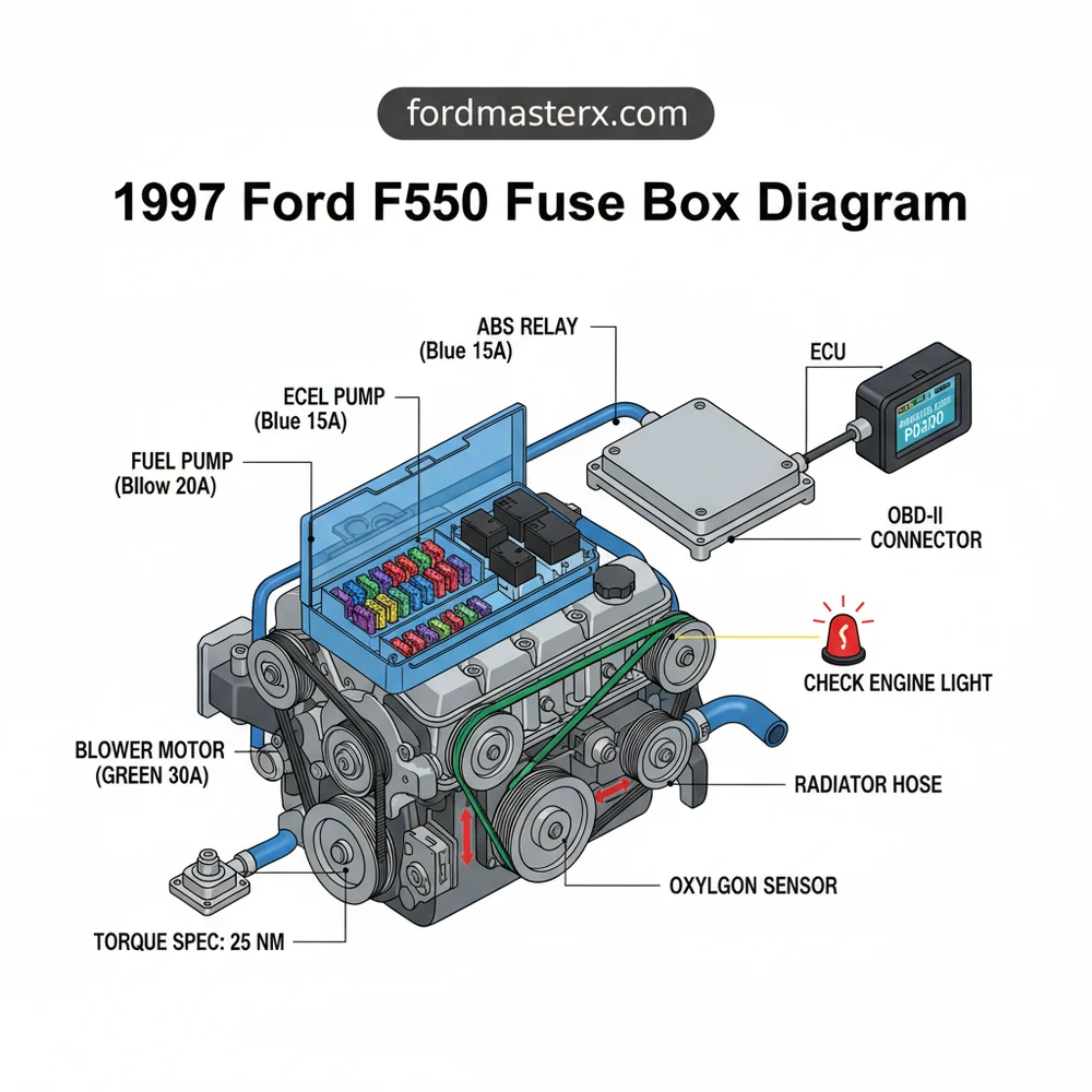
What does this diagram show?
The diagram provides a visual map of all fuse and relay positions, specifying the amperage for each circuit and identifying which electrical components they protect, such as the fuel pump, headlights, and the ECU, which is vital for engine management and performance.
How many connections does the fuse box have?
The interior panel features approximately 32 fuse slots, while the engine bay box contains several high-output maxi-fuses and relays. Each slot connects to specific wiring harnesses that distribute power across the vehicle’s electrical system, including the diagnostic link connector for scanners.
What are the symptoms of a bad fuse?
Common symptoms include sudden loss of power to specific components, an illuminated check engine light, or an OBD-II scanner failing to link. If the ECU fuse blows, the engine may crank but will not start, requiring a quick diagnostic code check and fuse replacement.
Can I replace a fuse myself?
Yes, replacing a fuse is a simple DIY task. Locate the correct panel, use the diagram to find the faulty circuit, and pull the fuse using a specialized tool. Ensure the engine is off and you use a replacement with the exact same amperage rating.
What tools do I need for this task?
You only need a plastic fuse puller tool, which is often found inside the fuse box cover, and a basic test light or multimeter. If you are disconnecting the battery, you may also need a wrench to meet the terminal torque spec upon reconnection.


