Ford Explorer Terrain Management System Fault Reset: The Definitive Technical Guide (2011–2025)
The modern automotive landscape is defined by the convergence of mechanical engineering and digital logic. Nowhere is this more apparent than in the Ford Explorer’s Terrain Management System™ (TMS). Introduced with the 5th Generation Explorer in 2011, the TMS represented a paradigm shift from traditional mechanical transfer case levers to a software-driven, mode-selectable algorithm that coordinates the vehicle’s powertrain, braking, and stability control systems. However, this sophistication introduces complexity. For owners of 2011 through 2025 models, the message “Terrain Management System Fault” is a ubiquitous and often misunderstood warning.
This report serves as an exhaustive technical dossier for technicians, advanced DIYers, and owners. It moves beyond superficial “quick fixes” to explore the root causes of TMS failures—ranging from voltage irregularities in the Battery Management System (BMS) to signal corruption in the Controller Area Network (CAN). Through a synthesis of technical service bulletins (TSBs), diagnostic telemetry, and community-verified data, this document establishes a definitive protocol for diagnosis and repair.
The Evolution of Terrain Management
The genesis of the Ford TMS can be traced back to Ford’s ownership of Land Rover. The system shares its DNA with Land Rover’s Terrain Response, operating on the principle that the driver should select the surface (Snow, Sand, Mud), and the vehicle should configure the hardware to match.
In the 5th Generation Explorer (2011–2019), the system utilizes a Front-Wheel-Drive (FWD) biased architecture with a transversely mounted engine and a Power Transfer Unit (PTU) sending torque to the rear. The 6th Generation (2020–Present) reversed this, utilizing a Rear-Wheel-Drive (RWD) biased platform with a longitudinal engine. Despite these mechanical differences, the software logic remains remarkably consistent, as do the failure modes.
Table 1: Terrain Management System Operational Parameters
| Drive Mode | Throttle Mapping | Transmission Logic | Traction Control (TCS) | Torque Split Bias |
| Normal | Linear | Economy/Comfort | Standard Intervention | FWD Biased (5th Gen) / Balanced (6th Gen) |
| Mud/Rut | Aggressive Tip-In | Holds Lower Gears | Desensitized (Allows Spin) | 50/50 Lock Simulation |
| Sand | Maximum Sensitivity | Delayed Upshifts | Aggressive Slip Allowance | High Rear Bias |
| Snow/Gravel | Retarded Response | Early Upshifts | High Sensitivity (No Spin) | Predictive Pre-Load |
| Hill Descent | Automated Braking | Locked 1st Gear | ABS Pump Cycling | N/A |
The “Christmas Tree” Phenomenon
The defining characteristic of a TMS fault is its sociability; it rarely travels alone. Owners typically report a cascade of warnings:
- Service AdvanceTrac
- Hill Descent Control Fault
- Check Brake System
- ABS Warning Light
- Terrain Management System Fault
This cluster, colloquially known as the “Christmas Tree” effect, occurs due to the hierarchical nature of the vehicle’s safety systems.1 The TMS is a high-level function that relies on valid data from lower-level subsystems (ABS wheel speeds, steering angle, engine torque). If a single low-level sensor fails (e.g., a wheel speed sensor), the TMS “faults out” because it lacks the data integrity required to safely modulate torque or braking. It is a failsafe state, not necessarily a failure of the TMS module itself.
TERRAIN MANAGEMENT
SYSTEM FAULT
Why your Ford Explorer disabled 4WD, and how to reset the error without breaking the bank.
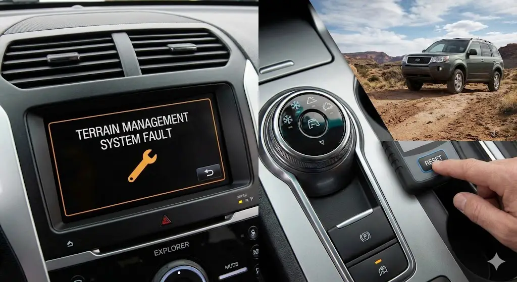
⚠️ The Dashboard Panic
The “Terrain Management System Fault” is one of the most common warnings on the Ford Explorer dashboard. While it sounds like a catastrophic transmission failure, it is rarely a mechanical issue.
This error triggers a “Fail-Safe” mode, disabling Intelligent 4WD, Hill Descent Control, and drive modes (Snow, Sand, Mud), reverting the vehicle to standard FWD or a fixed torque split to protect the drivetrain.
Why Does It Happen?
Analysis of reported faults shows that electrical sensors are the primary culprit, far outweighing mechanical failures.
ABS Wheel Speed Sensors
The #1 cause. If one wheel reports 0 MPH while others report 40 MPH, the computer disables Terrain Management to prevent damage.
Steering Angle Sensor
Located in the steering column. If it loses calibration, the car cannot calculate trajectory, disabling stability control.
Battery Voltage
Explorers are sensitive to voltage. An old battery can throw “Ghost Codes” for the 4WD module during startup.
Step-by-Step Reset Workflow
Before spending money on parts, follow this logical path to attempt a system reset.
The Cost Reality
The price gap between a DIY fix and a dealership visit is substantial. Since Wheel Speed Sensors are the most common cause, learning to swap them yourself can save over $200 per occurrence.
- SAVE DIY Sensor: A single Motorcraft sensor costs ~$45 online. It requires removing one wheel and one bolt (10mm).
- NOTE Diagnostic Fee: Most dealers charge 1 hour of labor ($150-$180) just to tell you which sensor failed.
- WARN PTU Failure: If the code indicates the Power Transfer Unit (PTU), costs skyrocket. This is mechanical, not electrical.
Estimated Repair Costs (USD)
The Electrical Pathology: Voltage, Entropy, and the BMS
The most prevalent, yet least diagnosed, cause of the Terrain Management System fault is electrical instability. Modern Ford vehicles are governed by a complex charging strategy known as the Battery Management System (BMS).
The Battery Management System (BMS) Logic
Unlike older vehicles where the alternator charged the battery continuously, the Explorer’s BMS monitors the battery’s State of Charge (SoC), temperature, and health via a current sensor located on the negative battery terminal.3 To improve fuel economy, the PCM commands the alternator to reduce or stop charging when the battery is deemed “full” or under low load.
The Failure Mode: As a battery ages, its internal resistance increases. The BMS detects this and may restrict electrical loads to preserve starting power. However, sensitive modules—specifically the Power Steering Control Module (PSCM) and the ABS module—require stable voltage reference signals (typically 5V) to interpret sensor data. If the system voltage fluctuates or drops below a critical threshold (even momentarily during cranking), these modules may fail their “handshake” with the main computer, triggering a communication code (U-Code) and disabling the TMS.
The “New Battery” Trap
A critical error owners make is replacing the battery without resetting the BMS monitor. If the BMS is not reset, the ECU retains the “aged battery” charging profile. It will effectively undercharge the new battery, leading to a recurrence of the TMS fault within days or weeks. This phenomenon has been widely documented in enthusiast communities and technical forums.
Reset Procedure: The High-Beam/Brake Method
While a diagnostic scan tool (like IDS or FORScan) is the official method for resetting the BMS, a manual override exists that requires no tools. This procedure forces the Body Control Module (BCM) to recalibrate its battery monitoring parameters.
Step-by-Step BMS Reset Protocol:
- Preparation: Ensure the vehicle is in Park (P) and all doors are closed.
- Ignition State: Press the Start button (without touching the brake) to enter Ignition ON / Engine OFF mode. The dashboard lights should illuminate.
- Sequence Initiation:
- Within 10 seconds, pull the high beam stalk (flash to pass) five (5) times.
- Immediately press and release the brake pedal three (3) times.
- Confirmation: Observe the battery icon on the instrument cluster. It will flash three times to confirm the reset command was accepted.
- Completion: Turn the ignition OFF. Upon the next startup, the BMS will begin learning the new battery’s capacity.
Sensor Network Analysis: The Data Stream
If voltage is stable, the investigation must pivot to the data stream. The TMS relies on a sensor fusion model comprising wheel speed, steering angle, yaw rate, and throttle position.
Wheel Speed Sensors (The ABS Connection)
The ABS sensors are the eyes of the TMS. Located at each wheel hub, they utilize the Hall Effect or Variable Reluctance principle to generate a frequency signal proportional to wheel rotation.11
Mechanism of Failure:
- Signal Noise: The sensors read a “tone ring” (a toothed magnetic ring) integrated into the wheel bearing or axle shaft. In rust-prone regions, corrosion can build up behind the sensor, pushing it away from the tone ring (rust jacking). This increases the air gap, weakening the signal.
- Debris Contamination: Metallic brake dust can accumulate on the magnetic sensor tip, creating “ghost” signals.
- Wiring Fatigue: The harness connecting the sensor to the body flexes with suspension travel. Over time, internal copper strands can break while the insulation remains intact, causing intermittent open circuits during turns.
Diagnostic Insight: A TMS fault that triggers specifically when turning, hitting a bump, or driving in rain is highly indicative of a wheel speed sensor or harness failure.
The Steering Angle Sensor (SAS)
The SAS informs the computer of the driver’s intended path. In the Explorer, this sensor is often integrated into the Steering Column Control Module (SCCM) or the Electric Power Assisted Steering (EPAS) rack.
The Drift Phenomenon: The SAS requires precise calibration. If the vehicle undergoes an alignment, or if suspension components (tie rods, control arms) are replaced, the physical “center” of the steering wheel may no longer match the electronic “center” (0 degrees).
- The Conflict: If the SAS reads 5 degrees right, but the Yaw Rate Sensor indicates the vehicle is moving straight, the AdvanceTrac system assumes the vehicle is sliding (understeer). It attempts to intervene, fails to correct the “slide” (because none exists), and eventually disables itself, triggering the “Service AdvanceTrac” and TMS faults.
The Yaw Rate and Lateral Accelerometer
Buried deep within the center console or under the seat is the Restraints Control Module (RCM), which houses gyroscopes measuring the vehicle’s rotation (yaw) and side-to-side force (lateral Gs). While less prone to failure than wheel sensors, these sensors can be confused by aftermarket suspension lifts or leveling kits that alter the vehicle’s center of gravity and rake.
Powertrain Interdependencies: Throttle and Transmission
The TMS does not just manage brakes; it actively manages engine torque. Consequently, faults in the powertrain can masquerade as TMS failures.
The Electronic Throttle Body (ETB) Crisis
One of the most widespread issues affecting the 5th Generation Explorer (specifically 2011–2016 models with the 3.5L Ti-VCT and 2.3L EcoBoost) is the failure of the Electronic Throttle Body.
TSB 16-0139 / CSP 16B32: Ford acknowledged a defect where the internal electrical contacts of the throttle motor potentiometer would develop high resistance due to contamination.
- Symptoms: The vehicle enters “Limp Mode” (reduced power), the Wrench light illuminates, and the TMS Fault message appears.
- Codes: P2111 (Throttle Actuator Control System – Stuck Open) and P2112 (Stuck Closed) are the smoking guns.
- The TMS Link: The TMS requires precise throttle modulation (e.g., damping throttle response in Snow mode). If the PCM detects any unreliability in throttle position control, it immediately disables the TMS to prevent run-away acceleration or lack of power in critical off-road situations.
Power Transfer Unit (PTU) Failures
The Power Transfer Unit is the mechanical heart of the AWD system in 5th Gen Explorers. It splits torque from the transaxle to the rear driveshaft.
- The Heat Problem: The PTU is packaged essentially inside the exhaust tunnel, adjacent to catalytic converters. The factory fill of gear oil (often touted as “lifetime”) degrades rapidly under this thermal stress, turning into sludge.
- The Fault: While purely mechanical wear (grinding bearings) doesn’t always throw a code, advanced failure can cause mechanical binding. If the 4WD control module detects that the rear driveshaft speed does not match the expected output ratio (due to internal clutch slip or binding), it will disable the AWD system and trigger a TMS fault to protect the driveline.
Generation 6 (2020+) Specific Faults
The 2020 redesign brought a new architecture and new failure modes. The shift to a RWD-based platform introduced the Front Axle Disconnect system, designed to improve fuel economy by physically decoupling the front CV axles when AWD is not needed.
TSB 23-2174: Front Axle Disconnect Failure
Owners of 2020–2021 Explorers often report a “Powertrain Malfunction/Wrench” light accompanied by TMS failure.
- Codes: DTCs C00A6 and C0631.
- Root Cause: The actuator that engages the front axle intermediate shaft fails, or the shaft itself suffers mechanical damage. This prevents the vehicle from entering 4WD.
- Correction: Ford released Technical Service Bulletin 23-2174, instructing technicians to replace the front axle disconnect actuator and the intermediate shaft with revised parts. This is a complex repair requiring significant disassembly of the front suspension.
Table 2: Comparison of Major Failure Modes by Generation
| Feature | 5th Gen Explorer (2011–2019) | 6th Gen Explorer (2020–Present) |
| Drivetrain Layout | FWD Biased (Transverse) | RWD Biased (Longitudinal) |
| Primary Weak Point | PTU Overheating / Throttle Body (ETB) | Front Axle Disconnect Actuator |
| Common Codes | P2111, P2112, C003X (Wheel Speed) | C00A6, C0631, U0253 |
| Steering Sensor | Inside EPAS Rack (Expensive) | Separate/Integrated (Varies) |
| Recall/TSB Focus | Electronic Throttle Body, EPAS | Front Intermediate Shaft, Software Updates |
Advanced Diagnostics: FORScan and Data Analysis
While parts cannons (replacing parts at random) are a common strategy, they are expensive. A scientific approach utilizing FORScan—a powerful diagnostic software package for Ford/Lincoln/Mazda vehicles—is recommended.
Understanding Code Families
To diagnose a TMS fault, one must distinguish between the types of Diagnostic Trouble Codes (DTCs):
- P-Codes (Powertrain): Engine and Transmission (e.g., P0300 Misfire, P2111 Throttle). These trigger the Check Engine Light and often disable TMS as collateral damage.
- C-Codes (Chassis): ABS, Suspension, Steering (e.g., C0031 Wheel Speed Sensor). These are the direct causes of “Service AdvanceTrac.”
- U-Codes (Network): Communication failures (e.g., U0100 Lost Comm with PCM). These often point to battery voltage issues or corroded harness connectors.22
The FORScan Oscilloscope Test
To verify a wheel speed sensor failure without guessing:
- Setup: Connect the OBDLink EX adapter to the laptop and vehicle. Launch FORScan.
- Module Selection: Navigate to the ABS Module (Anti-Lock Brake System).
- PID Selection: Select the PIDs for
WHEEL_SPD_FL(Front Left),WHEEL_SPD_FR,WHEEL_SPD_RL, andWHEEL_SPD_RR. - Data Logging: Switch to “Oscilloscope” view.
- Test Drive: Drive the vehicle in a straight line at 15-20 mph.
- Analysis: All four lines should overlap perfectly.
- Scenario A: One line stays flat at 0. Result: Dead sensor or broken wire.
- Scenario B: One line is “noisy” or spikes erratically. Result: Rust on tone ring or metal debris on sensor.
- Scenario C: All lines match, but fault persists. Result: Check Steering Angle Sensor (SAS) data.
Calibrating the Steering Angle Sensor (SAS) with FORScan
If the SAS is suspected (e.g., steering wheel is straight but FORScan reads STR_ANG = 15 degrees):
- Navigate to the Service Functions tab (Wrench icon).
- Select “Calibrate Steering Angle Sensor” (usually under PSCM or ABS).
- Ensure the physical steering wheel is perfectly level.
- Execute the function. The module will reset the current position as “0”.
Repair Protocols and Cost Analysis
Repairing the TMS system can range from a free software reset to a multi-thousand-dollar steering rack replacement.
Wheel Speed Sensor Replacement
This is the most common hardware repair.
- Diagnosis: Confirmed via C003X code.
- Part Cost: $45–$85 for OEM Motorcraft; $20–$40 for aftermarket.
- Labor: 1.0 Hours.
- Procedure: Lift vehicle, remove wheel, remove single 8mm bolt holding sensor to knuckle. Crucial Step: Clean the mounting surface of rust. If the sensor does not sit flush due to rust buildup (rust jacking), the new sensor will also fail. Apply dielectric grease to the O-ring.
Throttle Body (ETB) Replacement
- Diagnosis: Confirmed via P2111/P2112 code.
- Part Cost: $150–$
- Labor: 1.0 Hours.
- Procedure: Remove air intake tube, disconnect electrical connector, remove 4 bolts. Install new unit. Relearn: Disconnect battery negative terminal for 15 minutes to clear adaptive fuel trims and throttle position memory. Reconnect and idle for 15 minutes.
Steering Rack (EPAS) Replacement
This is the “nuclear option” for 5th Gen owners with internal sensor failures.
- Diagnosis: Persistent C-codes for Torque Sensor or Internal Module Failure.
- Part Cost: $800–$1,500.
- Labor: 4.0–6.0 Hours (Subframe removal often required).
- Total Cost: Can exceed $2,500 at a dealer.
- Note: This unit requires “As-Built” data programming via FORScan or IDS to function. You cannot simply swap it and drive; the car will not recognize the new module.
Table 3: 2025 Estimated Repair Costs (National Average)
| Repair Item | Part Cost (OEM) | Labor Time | Total Est. (Independent) | Total Est. (Dealer) |
| BMS Reset | $0 | 0.5 hrs | $60–$80 | $150–$180 |
| Wheel Speed Sensor | $65 | 1.0 hrs | $200 | $350 |
| Throttle Body | $220 | 1.5 hrs | $450 | $650 |
| Steering Angle Sensor | $180 | 2.5 hrs | $550 | $800 |
| 4WD Actuator (6th Gen) | $350 | 3.0 hrs | $800 | $1,200 |
Frequently Asked Questions (FAQs)
Q: Can I permanently disable the Terrain Management System to stop the warnings?
A: No. The system is integrated into the ABS and PCM. Disabling it would require disabling the entire ABS system, which renders the vehicle unsafe and illegal for road use. The warning is a symptom of a safety system failure, not just a feature failure.
Q: I replaced the ABS sensor, but the light is still on. Why?
A: Did you drive the vehicle? Unlike engine codes, ABS codes often require the vehicle to move so the module can verify the signal from the new sensor. Drive above 15mph for a few hundred yards. If the light persists, verify the tone ring isn’t damaged or dirty, and clear the codes manually with a scanner.
Q: My 2016 Explorer goes into Limp Mode on the highway. Is this the TMS?
A: This is classic Electronic Throttle Body (ETB) failure behavior (TSB 16-0139). While the TMS fault message will appear, the root cause is the throttle body. Replacing the ETB is the priority.
Q: What is the “As-Built” data mentioned in repairs?
A: As-Built data is the factory hexadecimal code string that defines your vehicle’s specific configuration (options, gear ratio, tire size). When replacing modules like the ABS or PSCM, you must program this data into the new unit using FORScan, or the module will not function.
Q: Does the “Wrench” light mean I need an oil change?
A: No. In Ford vehicles, the Wrench icon indicates a Powertrain Malfunction or Electronic Throttle Control error. It is distinct from the “Service Engine Soon” (Check Engine) light. It signifies a non-emissions related fault that typically results in Limp Mode.
Conclusion
The “Terrain Management System Fault” is a complex signal emerging from a sophisticated network of sensors and modules. While the warning is intimidating, the majority of cases in the Ford Explorer fleet are resolved through three primary avenues:
- Restoring Electrical Integrity: Performing a proper BMS reset and ensuring battery health.
- Restoring Sensor Data: Cleaning or replacing ABS wheel speed sensors.
- Restoring Airflow Control: Replacing the Electronic Throttle Body on susceptible 5th Gen models.
For the owner, the path to resolution lies in systematic diagnosis rather than panic. By utilizing accessible tools like the High-Beam/Brake reset procedure and FORScan software, the root cause can be isolated efficiently, transforming a potential multi-thousand-dollar dealership visit into a manageable repair. As these vehicles age, maintaining the integrity of the wiring harnesses and tone rings will become increasingly vital to keeping the Terrain Management System operational and the dashboard free of warning lights.