Ford Explorer Heater Hose Diagram: Complete Guide
The Ford Explorer heater hose diagram illustrates the routing from the engine block to the heater core. It identifies the inlet and outlet hoses, the control valve, and the connection points at the firewall. This layout is vital for identifying coolant leaks and ensuring correct system configuration during hose replacement.
📌 Key Takeaways
- Identifies coolant flow from engine to heater core
- Locate the heater control valve and inlet/outlet ports
- Never work on a hot cooling system to avoid burns
- Use the layout to check for cracked or bulging hoses
- Essential for troubleshooting low heater output or leaks
Navigating the engine bay of a mid-size SUV can often feel like solving a complex puzzle, especially when dealing with the intricate cooling system. If you are experiencing a lack of cabin heat or noticing a puddle of coolant under your vehicle, finding an accurate 2006 Ford Explorer heater hose diagram is the first step toward a successful repair. This comprehensive guide is designed to help DIY enthusiasts and vehicle owners understand the complex network of hoses that transport warm coolant from the engine block to the heater core. By the end of this article, you will be able to identify every major component, understand the flow of the system, and execute a replacement with professional-level confidence.
The 2006 Ford Explorer utilizes two primary engine configurations: the 4.0L V6 and the 4.6L V8. While the general principle of the heater hose system remains the same, the routing and specific connector locations vary significantly between these two powerplants. Always verify your engine type before purchasing replacement parts.
Understanding the Heater Hose System Configuration
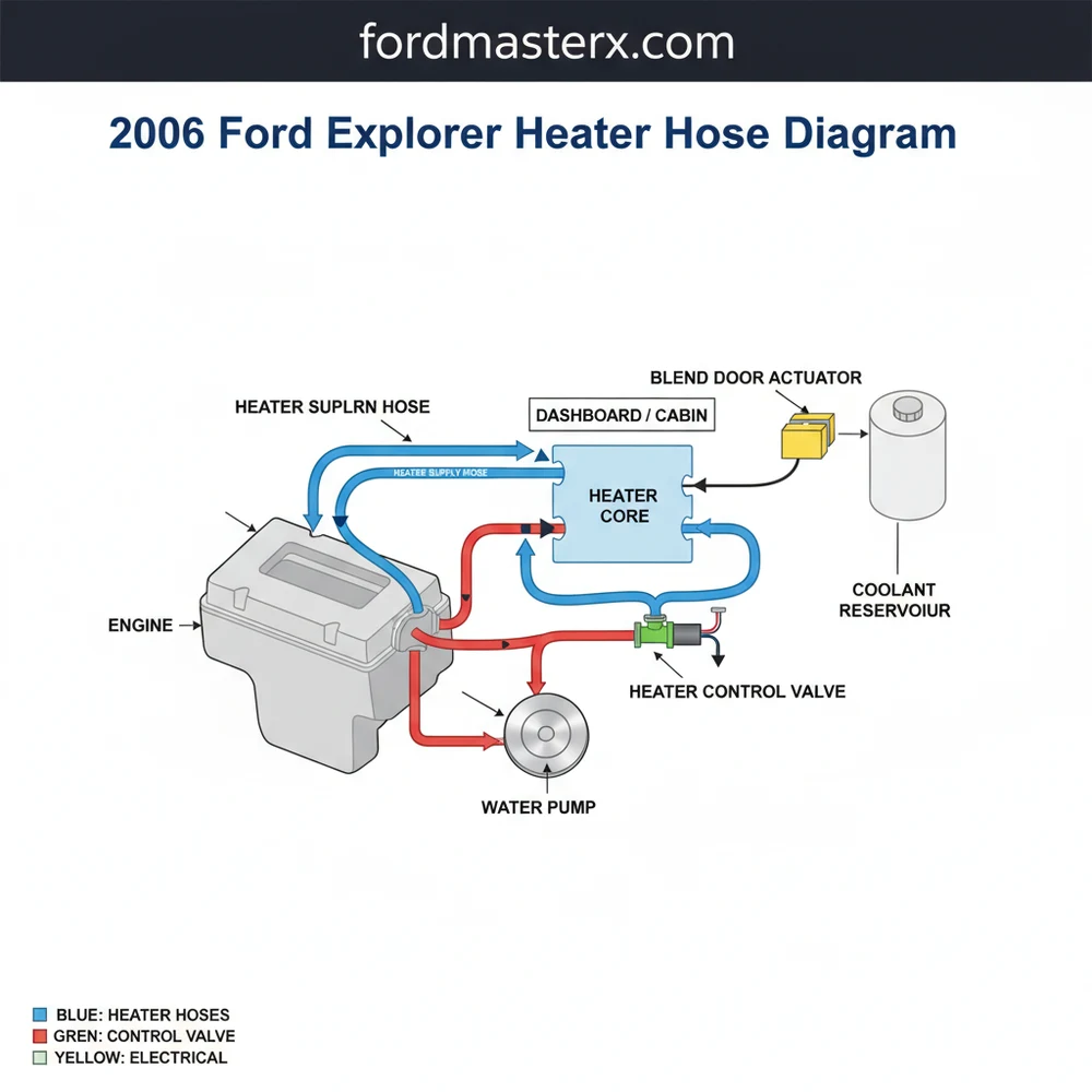
The heater hose system in a 2006 Ford Explorer is a critical subsystem of the larger engine cooling layout. Its primary function is to circulate hot engine coolant through the heater core, which sits inside the dashboard. This structure allows the HVAC system to blow air across the hot core and provide warmth to the cabin. The system consists of two main hoses: the inlet (supply) hose and the outlet (return) hose. The inlet hose typically draws hot coolant from the engine block or the thermostat housing, while the return hose sends the cooled liquid back toward the water pump or the radiator to be reheated.
A detailed overview of the schematic reveals that the 2006 model often incorporates a “Y-connector” or a “T-pipe” assembly, particularly in models equipped with rear auxiliary heating. This configuration adds complexity to the blueprint, as it requires additional lines running along the undercarriage to a secondary heater core located in the rear of the vehicle. These hoses are often made of reinforced EPDM rubber, though the connectors themselves are frequently constructed from high-heat plastic, which can become brittle over time and lead to catastrophic leaks.
When looking at a blueprint of this system, you will notice that the hoses are color-coded in some technical manuals—red usually indicating the high-pressure supply line and blue representing the lower-pressure return line. The layout is designed to be as direct as possible to minimize heat loss, but the crowded nature of the Ford Explorer engine bay necessitates several bends and custom-molded shapes. Understanding these specific molds is essential, as universal straight hoses will often kink and restrict coolant flow, leading to engine overheating.
[DIAGRAM_PLACEHOLDER: 2006 Ford Explorer Heater Hose Layout showing Engine Block to Firewall Connections, including T-Connectors and Quick-Disconnect Fittings]
Step-By-Step Guide to Reading the Diagram and Replacing Hoses

Interpreting a technical schematic requires a systematic approach. To effectively use a 2006 Ford Explorer heater hose diagram, you must first orient yourself with the “firewall”—the metal barrier between the engine and the cabin. This is where the heater core nipples protrude. Once you have identified these two points, you can trace the lines back to the engine. Follow these steps to translate the diagram into a physical repair.
- ✓ Step 1: Identify the Component Locations – Locate the thermostat housing at the front or top of the engine and the heater core inlet/outlet at the rear of the engine bay near the passenger side firewall. Use the diagram to confirm which hose connects to which port, as reversing them can sometimes cause gurgling noises in the dash.
- ✓ Step 2: Prepare Your Tools and Safety Gear – You will need long-reach needle-nose pliers or specialized hose clamp pliers, a coolant drain pan, and a screwdriver. Ensure the engine is completely cool to avoid severe burns from pressurized steam.
- ✓ Step 3: Drain the Cooling System – Open the radiator drain petcock (usually located on the bottom driver’s side) and collect the fluid. You do not need to drain the entire system for a heater hose change, but the level must be below the heater core ports to prevent a mess.
- ✓ Step 4: Disconnect the Quick-Connect Fittings – Many 2006 Explorers use plastic quick-connectors at the firewall. These often require a specific release tool or a firm squeeze on the locking tabs. If the plastic is brittle, be prepared to replace the connector entirely.
- ✓ Step 5: Route the New Hoses – Following the layout provided in your schematic, thread the new hoses through the engine bay. Ensure they are not touching moving parts like the cooling fans or resting against high-heat components like the exhaust manifold.
- ✓ Step 6: Secure Clamps and Test – Tighten all constant-tension or worm-gear clamps. Refill the system with a 50/50 mix of the recommended coolant and perform a “burping” procedure to remove trapped air.
Never open the radiator cap while the engine is hot. The cooling system is under high pressure, and hot coolant can spray out, causing third-degree burns. Always wait at least one hour after driving before beginning work.
Common Issues & Troubleshooting via the Schematic

A heater hose diagram is more than a map for installation; it is an essential troubleshooting tool. One of the most frequent problems encountered by 2006 Explorer owners is a failure of the heater control valve or the plastic “Y” pipe. By looking at the system blueprint, you can see exactly where these plastic junctions are located. If you notice a “sweet” smell inside the cabin or see steam rising from the back of the engine, the diagram helps you pinpoint whether the leak is at the firewall connection or further up the line at the engine block.
Another common issue is airlock, where an air bubble becomes trapped in the highest point of the hose layout. This prevents coolant from reaching the heater core, resulting in cold air blowing from the vents even when the engine is at operating temperature. By analyzing the structure of the hoses, you can identify the “high points” where air is likely to gather and use that information to properly bleed the system. If you find that one hose is hot while the other is cold, the schematic confirms that there is a blockage within the heater core itself, necessitating a flush or replacement.
Tips & Best Practices for Cooling System Longevity
To ensure your 2006 Ford Explorer remains reliable, follow these professional maintenance tips. First, always use high-quality, vehicle-specific hoses. While universal hoses are cheaper, the pre-molded configuration of the OEM-style hoses ensures they don’t rub against the chassis or kink, which preserves the flow rate of the entire system. When replacing a hose, it is best practice to replace the clamps as well. Constant-tension clamps (the springy kind) are generally preferred over worm-gear clamps because they adjust to the expansion and contraction of the rubber as it heats and cools.
When refilling the coolant, use a “no-spill” funnel that attaches directly to the radiator neck. This allows you to run the engine with the funnel half-filled, making it significantly easier to see air bubbles escaping and ensuring the heater hose system is completely primed.
Regularly inspect the plastic connectors shown in your blueprint. In the 2006 model year, Ford utilized several composite plastic components that are prone to hairline fractures. If you see any white or orange crusty residue (dried coolant) around these fittings, replace them immediately before they fail. Finally, always use the coolant type specified in your owner’s manual—typically Motorcraft Gold for this era—as mixing different types of coolant can lead to sludge buildup that will clog the narrow passages of the heater core, rendering your new hoses useless. By following the 2006 Ford Explorer heater hose diagram and adhering to these best practices, you can maintain a comfortable cabin temperature and protect your engine from the dangers of overheating.
Step-by-Step Guide to Understanding the Ford Explorer Heater Hose Diagram: Complete Guide
Identify – Start by identifying the specific hose connections on the firewall using the diagram.
Locate – Locate the heater control valve within the system configuration to check for vacuum leaks.
Understand – Understand how the layout routes coolant past the engine block to the heater core.
Connect – Connect the new hoses according to the structural diagram to ensure correct flow direction.
Verify – Verify that all clamps are secure and leak-free by pressure testing the system.
Complete – Complete the repair by bleeding air from the cooling system and refilling the reservoir.
Frequently Asked Questions
Where is the heater hose located?
The heater hoses are located at the rear of the engine compartment, connecting the engine block to the heater core at the firewall. You can find them by looking for two rubber tubes protruding from the passenger side dashboard area into the engine bay near the top of the motor.
What does the heater hose diagram show?
The diagram shows the path coolant takes from the engine to the heater core and back. It identifies the inlet and outlet hoses, the heater control valve, and the specific connection points. This visual guide ensures the system configuration is correctly understood before performing any maintenance or repairs.
How many connections does the heater hose system have?
Most configurations feature two primary hoses: an inlet and an outlet. Each hose typically has two connection points—one at the engine and one at the firewall. Depending on the specific engine type, there may also be vacuum lines connected to a heater control valve within the hose structure.
What are the symptoms of a bad heater hose?
Symptoms of a failing hose include visible coolant leaks under the vehicle, a sweet smell inside the cabin, and engine overheating. You might also notice the heater is blowing cold air or see physical signs of wear like cracking, bulging, or softness when squeezing the hose component.
Can I replace the heater hoses myself?
Yes, replacing heater hoses is a common DIY task for most owners. As long as you have basic tools and follow the layout provided in the diagram, you can swap them out in about an hour. Always ensure the engine is completely cool before starting to prevent serious burns.
What tools do I need for heater hose replacement?
To replace these hoses, you will need a set of hose clamp pliers or standard needle-nose pliers, a screwdriver, and a drain pan for catching coolant. It is also helpful to have fresh coolant on hand to refill the system once the new hose structure is installed.