Ford Expedition 5.4 Vacuum Hose Diagram: HVAC Guide
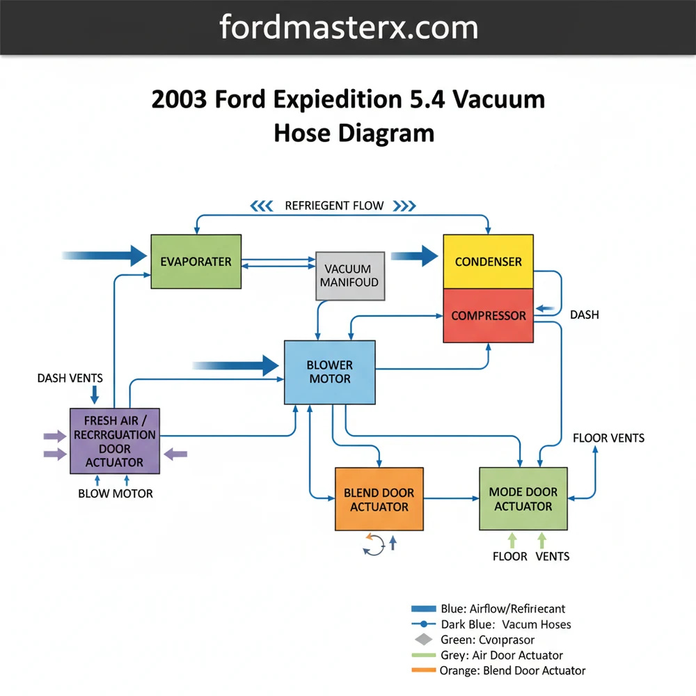
The 2003 Ford Expedition 5.4 vacuum hose diagram illustrates how engine vacuum controls the HVAC blend doors and vents. It maps the connection from the intake manifold to the vacuum reservoir and dashboard controls. This ensures conditioned air flows through the evaporator and into the cabin correctly when requested by the driver.
📌 Key Takeaways
- Identifies the vacuum source for HVAC vent control
- Locates the vacuum reservoir critical for consistent air distribution
- Highlights the connection between engine vacuum and blend door actuators
- Helps diagnose ‘defrost-only’ air flow symptoms
- Ensures proper integration between mechanical vacuum and electrical blower motor components
The 2003 Ford Expedition, equipped with the 5.4L Triton V8, is a powerhouse of a full-size SUV, but its performance is heavily reliant on a complex web of vacuum hoses. For DIY enthusiasts, understanding the vacuum system is essential for maintaining engine efficiency, ensuring smooth idling, and keeping the 4WD system functional. A single cracked rubber elbow or a brittle plastic line can lead to a cascade of issues, from “Check Engine” lights to a complete loss of power steering assist or braking performance. This guide provides a comprehensive breakdown of the vacuum hose architecture for the 2003 Ford Expedition 5.4L, helping you navigate the engine bay with confidence.
Main Components and Vacuum System Features
The vacuum system in the 5.4L Triton engine serves three primary purposes: emissions control, engine performance management, and auxiliary system operation (such as the HVAC vents and 4WD engagement). Understanding where the vacuum originates and where it goes is the first step in mastering the diagram.
- The Intake Manifold: This is the primary source of vacuum. The 5.4L engine generates significant “manifold vacuum” during the intake stroke. Multiple ports are located on the upper intake plenum, usually behind the throttle body or near the firewall.
- PCV (Positive Crankcase Ventilation) System: This is arguably the most critical vacuum circuit. It draws crankcase vapors back into the intake to be burned. In the 2003 model, the PCV valve is located on the passenger side valve cover. A thick rubber hose (typically 5/8″ ID) runs from the valve to a port on the rear of the intake manifold.
- EGR (Exhaust Gas Recirculation) System: This system uses vacuum to open the EGR valve, allowing exhaust gases to re-enter the combustion chamber to lower NOx emissions. Key components include the EGR Vacuum Regulator (EVR) solenoid and the DPFE sensor.
- EVAP (Evaporative Emission) System: This system prevents fuel vapors from escaping into the atmosphere. The Vapor Canister Purge Valve, usually mounted near the firewall or on the driver-side fender well, uses vacuum to pull fuel vapors from the charcoal canister into the engine.
- Brake Booster: A large-diameter vacuum hose (usually reinforced 11/32″ or 3/8″) runs from the intake manifold to the brake booster. This provides the power assist necessary for braking.
- IWE (Integrated Wheel Ends) / 4WD System: Unique to the Expedition and F-150, the 4WD system uses vacuum to disengage the front hubs. When the engine is running and in 2WD, vacuum is applied to the hubs. When you switch to 4WD, the solenoid cuts the vacuum, and internal springs engage the hubs.
How to Use and Read the Vacuum Diagram
Locating a physical diagram for the 2003 Ford Expedition is easiest by looking at the VECI (Vehicle Emission Control Information) sticker. This is typically found on the underside of the hood or on the radiator shroud. However, these diagrams use technical shorthand that can be confusing. Here is how to translate the common abbreviations found on Ford diagrams:
- MAN VAC: Manifold Vacuum. This is the “source” line connected directly to the intake.
- VRESER: Vacuum Reservoir. A plastic tank (often shaped like a ball or a box) that stores vacuum for use when the engine is under high load (low vacuum).
- EVR: EGR Vacuum Regulator. The solenoid that tells the EGR valve when to open.
- VCV: Vacuum Control Valve.
- CANP: Canister Purge Solenoid (part of the EVAP system).
- SOL V: Solenoid Valve.
When reading the diagram, solid lines typically represent hard plastic tubing, while dashed or thicker lines represent rubber hoses. On the 2003 Expedition, the vacuum lines are often color-coded for easier identification during assembly, though these colors may fade over 20 years. Common colors include Red (Main Vacuum Source), White (EGR Control), and Green (EVAP Source).
Detailed Routing and Locations

To accurately trace the lines, start at the Vacuum Tree. On the 5.4L engine, the vacuum source is primarily found at the rear of the intake manifold. This area is notoriously difficult to see and often requires a mirror or removing the engine’s plastic decorative cover.
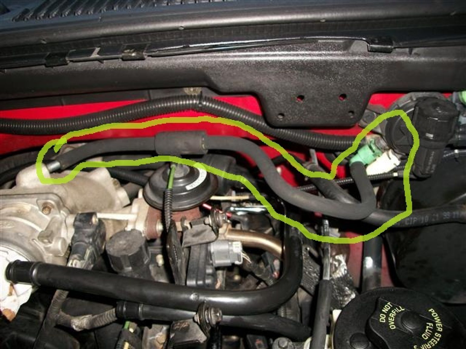
The PCV Line: Follow the hose from the passenger-side valve cover. It wraps around the back of the engine. On many 2003 models, this hose is insulated with a foam sleeve. If you feel “squishy” rubber or see oil residue, the hose is failing.
The 4WD Solenoid: Look at the firewall on the passenger side, near the battery. You will see a small solenoid with two vacuum lines and an electrical connector. One line goes to the vacuum reservoir, and the other heads down toward the front axles. This system is a frequent culprit for grinding noises in the front end.
HVAC Vacuum: A very thin black plastic line passes through the firewall on the passenger side. This line controls the “doors” inside your dash that switch air from the floor to the defrost vents. If your air only blows out of the defroster regardless of the setting, this tiny line is likely snapped or disconnected.
Troubleshooting Common Vacuum Issues
If your 2003 Expedition is experiencing a rough idle, poor fuel economy, or a “hissing” sound under the hood, you likely have a vacuum leak. Here is how to troubleshoot like a pro:
1. The Visual and Audible Inspection
With the engine running, listen for a high-pitched whistling or hissing sound. Use a length of garden hose or a mechanic’s stethoscope (with the probe removed) to pinpoint the sound. Move the hose around the intake manifold gaskets and the various rubber junctions.
2. The “Smoke Test”
This is the most effective DIY method. You can purchase or build a simple smoke machine that pumps thick smoke into the vacuum system through a main port (like the brake booster line) while the engine is off. Smoke will billow out of any crack or hole, no matter how small. This is particularly useful for finding leaks in the hard-to-reach PCV elbow at the back of the engine.
3. Monitoring Fuel Trims
If you have an OBD-II scanner, look at the Long Term Fuel Trims (LTFT). If the numbers are high (above 10-15%), the computer is adding extra fuel to compensate for unmetered air entering through a vacuum leak. If the trims drop back to normal when you increase the engine speed to 2,500 RPM, it is a confirmed vacuum leak (since vacuum is strongest at idle and weakest under load).
4. Soapy Water Method
For the 4WD system, which is a pressurized/vacuum-balanced system, you can spray a mixture of dish soap and water on the lines and IWE actuators. While the engine is running in 2WD, look for bubbles or areas where the liquid is being sucked into a crack.
Maintenance Tips for DIYers
Maintaining the vacuum system on a 20-year-old vehicle requires a proactive approach. Rubber degrades over time due to the extreme heat cycles of the 5.4L Triton engine.
- Replace with Silicone: When replacing old rubber vacuum lines, consider using high-temperature silicone hosing. It is more resistant to heat-rotting and will likely outlast the vehicle.
- Check the Check-Valves: Many vacuum lines have small plastic one-way check valves. These ensure vacuum remains in the system even when the engine is under load. Remove them and blow through them; they should only allow airflow in one direction.
- Zip-Tie the Ends: Because the plastic ports on the engine can become slick with oil over time, use small nylon zip ties on the ends of your vacuum hoses to create a permanent, air-tight seal.
- Don’t Forget the Reservoir: The vacuum reservoir (the “black box” or “ball”) can sometimes develop hairline cracks. If you’ve checked all the hoses and still have a leak, inspect the reservoir itself, usually hidden behind the battery tray or inside the passenger-side fender.
By systematically following the routing from the intake manifold to each component—PCV, EGR, EVAP, and 4WD—you can maintain the performance of your 2003 Ford Expedition. Most vacuum repairs are inexpensive in terms of parts but require patience and a steady hand to navigate the tight spaces of the engine bay. Keeping your vacuum system airtight is the best way to ensure your 5.4L Triton runs smoothly for another 100,000 miles.
Step-by-Step Guide to Understanding the Ford Expedition 5.4 Vacuum Hose Diagram: Hvac Guide
Identify the vacuum source at the 5.4L engine’s intake manifold port.
Locate the vacuum reservoir and inspect the check valve for proper one-way operation.
Understand how the main supply line enters the firewall to reach the HVAC controls.
Connect a handheld vacuum pump to individual actuator lines to test for leaks.
Verify that switching dash controls correctly routes air from the blower motor to different vents.
Complete the repair by securing all loose hoses with zip ties to avoid heat damage.
Frequently Asked Questions
Where is the vacuum reservoir located?
The vacuum reservoir on a 2003 Ford Expedition is typically located behind the battery tray on the passenger side of the engine bay. This plastic box stores vacuum pressure to ensure HVAC doors function consistently even during periods of low engine vacuum, such as under heavy acceleration or uphill driving.
What does the HVAC vacuum diagram show?
This diagram shows the routing of vacuum lines from the 5.4L engine’s intake manifold to the vacuum reservoir, then through the firewall to the HVAC control head. It details how the system directs air toward the evaporator or heater core to manage cabin temperature and vent selection automatically.
How many connections does the HVAC vacuum solenoid have?
Most HVAC vacuum solenoids in this system feature three primary connections: a vacuum supply from the engine or reservoir, a vent port to release pressure, and a control line going to specific actuators. These ensure precise movement of the internal HVAC blend and mode doors for optimal comfort.
What are the symptoms of a bad vacuum line?
The most common symptom is air only blowing through the defroster vents regardless of the dash setting. Other signs include the compressor cycling improperly, a lack of cool air from the evaporator, or a hissing sound behind the dashboard, indicating a leak in the vacuum circuit rather than refrigerant loss.
Can I replace these vacuum hoses myself?
Yes, replacing these hoses is a straightforward DIY task. You will need to identify brittle sections and replace them with matching rubber vacuum tubing. Be careful when working near the condenser and blower motor areas, ensuring all connections are tight to maintain proper system pressure and HVAC functionality.
What tools do I need for vacuum testing?
You primarily need a handheld vacuum pump with a gauge, a set of pliers for hose removal, and replacement vacuum tubing. A basic multimeter is also helpful to check electrical signals to the blower motor or compressor clutch if the vacuum system itself appears to be functioning correctly.


