Ford 6.7 Powerstroke Engine Diagram: Complete Guide
A Ford 6.7 Powerstroke engine diagram provides a visual map of the V8 diesel’s layout, highlighting the turbocharger, fuel rails, cooling system, and electrical sensors. It is essential for locating components when a diagnostic code appears or when performing routine maintenance tasks to ensure proper engine performance and reliability.
📌 Key Takeaways
- Identifies location of critical sensors, fuel systems, and mechanical parts.
- The turbocharger and high-pressure fuel pump are core components to identify.
- Always verify every torque spec to avoid damaging the engine’s aluminum components.
- Use the diagram alongside an OBD-II scanner for accurate part identification.
- Refer to this diagram during complex repairs or when tracking electrical shorts.
Navigating the complexities of a modern diesel engine requires more than just mechanical intuition; it demands a precise visual reference. The ford 6.7 powerstroke engine diagram serves as a foundational map for technicians and truck owners alike, offering a clear view of the unique “Scorpion” architecture that defines this powerplant. Whether you are attempting to locate a specific sensor to clear a stubborn fault code or performing a routine inspection of the cooling system, having a reliable diagram is the difference between a successful repair and a costly mistake. This article provides an exhaustive breakdown of the engine’s layout, ensuring you can identify every critical component from the high-pressure fuel rails to the intricate cooling loops.
Understanding the Ford 6.7 Powerstroke Engine Diagram
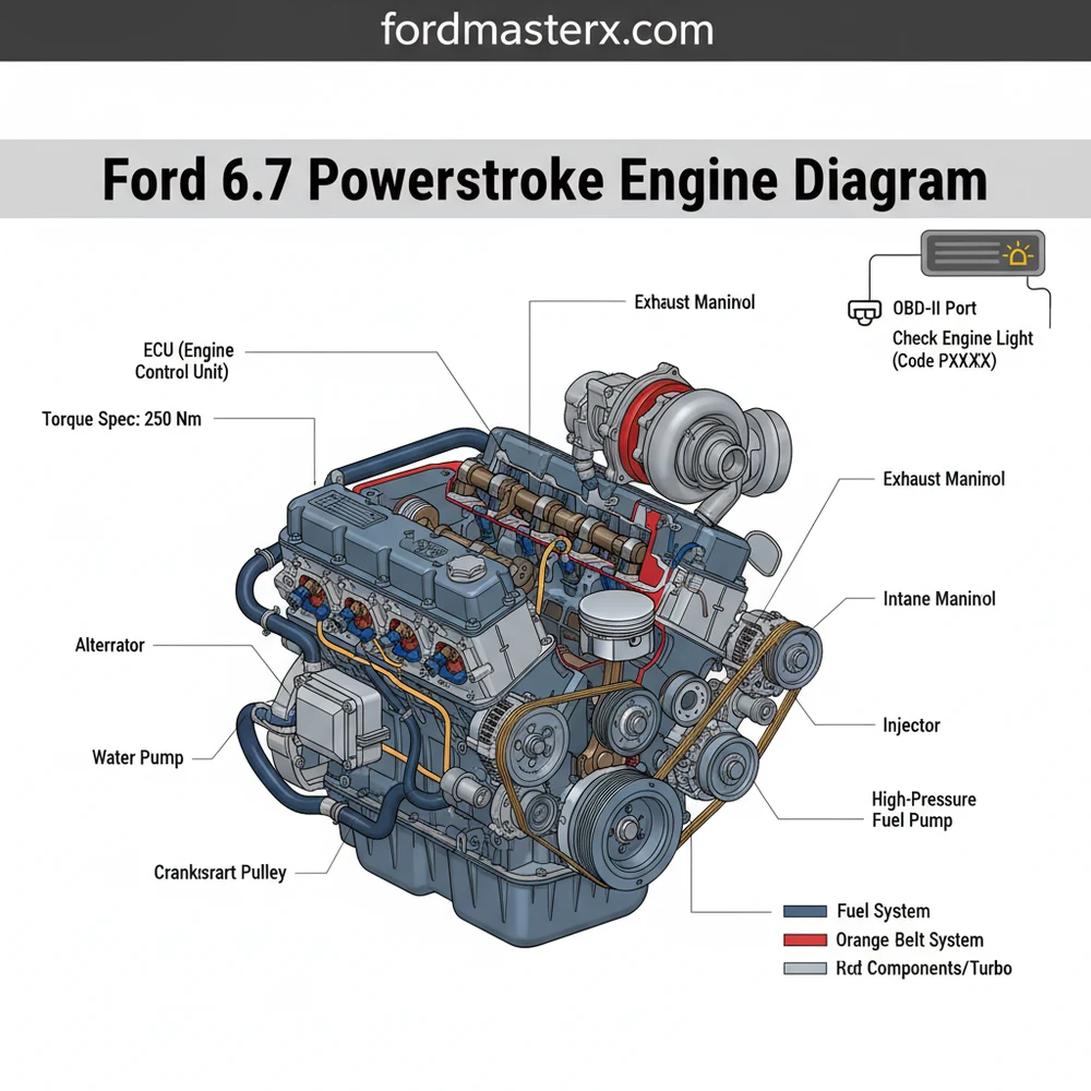
The architecture of the 6.7-liter Powerstroke is distinct from its predecessors due to its reverse-flow cylinder head design. In a standard V8, the exhaust manifolds are on the outside of the engine block, but in this configuration, the exhaust exits into the “valley” of the engine where the turbocharger is mounted. When looking at a ford 6.7 powerstroke engine diagram, you will notice the central placement of the Single Sequential Turbocharger (SST) or the later-generation variable geometry turbochargers. This design significantly reduces turbo lag and improves thermal efficiency by keeping the exhaust gasses hot as they enter the turbine.
The diagram further illustrates the dual cooling systems, a hallmark of this engine’s design. You will see two separate radiators and two distinct coolant flow paths. The primary system handles the engine block and cylinder heads, while the secondary system manages the charge air cooler, fuel cooler, and transmission oil cooler. Identifying these separate loops on the diagram is essential for troubleshooting overheating issues. Furthermore, the diagram highlights the location of the ECU (Engine Control Unit), which acts as the brain of the operation, receiving data from dozens of sensors to manage fuel timing, boost pressure, and emissions.
Visually, the diagram will often use color-coding to differentiate between the high-pressure fuel system and the air induction system. The fuel system, centered around the CP4.2 high-pressure pump, is a critical area of focus. The diagram shows how fuel travels from the tank, through the primary and secondary filters, and into the injectors at pressures that can exceed 29,000 psi. Understanding this path is vital for anyone performing fuel system maintenance or diagnosing a “crank but no start” condition.
The 6.7 Powerstroke utilizes a Compacted Graphite Iron (CGI) block, which provides immense strength while reducing overall weight. This material choice is a key reason the engine can handle the high combustion pressures required for its massive torque output.
Step-by-Step Guide to Interpreting and Using the Diagram

Reading a ford 6.7 powerstroke engine diagram effectively requires a systematic approach. Follow these steps to translate the 2D image into real-world mechanical action.
- Orient the Perspective: Most diagrams are drawn from the front of the vehicle looking toward the firewall. Identify the accessory belt (serpentine belt) at the front to establish your “North.” This will help you distinguish between the driver side (Bank 2) and the passenger side (Bank 1).
- Locate the Primary Control Systems: Find the ECU and the OBD-II interface connection points. In the diagram, these are often represented as a central hub with radiating lines going to various sensors like the Mass Air Flow (MAF) or the Exhaust Gas Temperature (EGT) sensors.
- Trace the High-Pressure Fuel Path: Follow the lines from the fuel tank to the engine-mounted fuel filters. Identify the CP4 pump in the valley. If you are diagnosing a diagnostic code related to fuel pressure, this path is where you will look for leaks or blockages.
- Map the Dual Cooling Loops: Use the diagram to identify which hoses belong to the high-temperature circuit (engine) and which belong to the low-temperature circuit (intercooler). This is crucial when refilling fluids to ensure no air pockets remain in either system.
- Identify the Valvetrain and Timing: While the 6.7 uses a timing chain to drive the high-pressure pump, the camshaft is actually gear-driven. Use the diagram to locate the access points for these internal components if you are performing a major overhaul.
- Analyze the Accessory Drive: Locate the accessory belt routing. The diagram should show the path around the alternator, AC compressor, and water pump. This is the first place to look if you hear squealing or lose power steering.
- Check the Emissions System: Trace the path from the exhaust manifolds to the Diesel Particulate Filter (DPF) and the Selective Catalytic Reduction (SCR) system. This is where most check engine light triggers originate in modern diesel trucks.
Never crack open a fuel line while the engine is running or immediately after shutdown. The 6.7 Powerstroke fuel system operates at extreme pressures that can cause skin penetration and severe injury. Always wait at least 10 minutes for pressure to bleed off.
To perform work based on the diagram, you will need a standard set of metric sockets, a high-quality OBD-II scanner, and a precision torque wrench. Many components on this engine have a very specific torque spec that must be followed to prevent leaks or metal fatigue, especially when dealing with the aluminum cylinder heads.
Common Issues and Troubleshooting via the Diagram

The ford 6.7 powerstroke engine diagram is an invaluable troubleshooting tool when a check engine light appears on your dashboard. One of the most common issues involves the Exhaust Gas Temperature (EGT) sensors. By using the diagram, you can quickly locate which of the four sensors is failing based on the diagnostic code provided by your scanner (e.g., P0544 for Sensor 1).
Another frequent problem is a leak in the secondary cooling system. Because there are two separate systems, owners often get confused about which reservoir to check. The diagram clearly labels the coolant flow for the intercooler system, allowing you to trace the hoses back to the secondary radiator. If you notice a drop in performance or a “reduced engine power” message, the diagram can help you find the charge air cooler boots, which are prone to cracking or slipping off under high boost.
Oil leaks are another area where the diagram shines. The turbocharger oil feed and return lines are located deep in the valley. Without a diagram, identifying the source of a valley leak is nearly impossible. By following the diagram’s layout, you can distinguish between a simple turbo o-ring leak and a more serious high-pressure fuel pump leak.
Pro Tips and Best Practices for Maintenance
To keep your 6.7 Powerstroke running at its peak, follow these industry best practices derived from years of mechanical experience:
- ✓ Monitor Fuel Quality: Since the CP4 pump is sensitive to water and debris, always use high-quality fuel and change your filters every 15,000 miles. Refer to your diagram to ensure you are draining the water separator correctly.
- ✓ Stick to the Torque Spec: When replacing items like the fuel injectors or the accessory belt tensioner, always use a calibrated torque wrench. Over-tightening can strip the threads in the CGI block or aluminum heads.
- ✓ Use an OBD-II Monitor: Instead of waiting for a check engine light, use a digital monitor to keep an eye on EGTs, soot levels, and oil temperature in real-time.
- ✓ Inspect the Accessory Belt: Check the belt for fraying or glazing every 30,000 miles. A snapped belt on this engine will result in an immediate loss of the water pump, leading to rapid overheating.
When tracing a diagnostic code, always check the wiring harness for rodent damage. The soy-based wiring insulation used in many modern vehicles is attractive to pests. Your diagram will show the routing of the main harness, helping you find hidden bite marks.
In conclusion, mastering the ford 6.7 powerstroke engine diagram is the most effective way to demystify this complex machine. By understanding the relationship between the ECU, the dual cooling systems, and the high-pressure fuel delivery, you move from guesswork to precision maintenance. Whether you are a DIY enthusiast or a professional, keeping a detailed diagram in your toolbox ensures that your Powerstroke remains a reliable workhorse for hundreds of thousands of miles. Always prioritize safety, use the correct tools, and consult your diagram before turning the first wrench.
Frequently Asked Questions
Where is the ECU located?
The Engine Control Unit (ECU) on a 6.7 Powerstroke is typically mounted on the driver’s side firewall within the engine bay. It is housed in a protective casing with multiple large wire harness connectors plugged into it, serving as the primary brain for engine management and sensor processing.
What does the Ford 6.7 Powerstroke engine diagram show?
This diagram illustrates the physical layout of the 6.7L Scorpion diesel engine, including the ‘hot-side’ turbocharger configuration, fuel injectors, EGR system, and cooling paths. It allows users to visualize how internal systems interact and helps in identifying specific sensors and mechanical assemblies for repair or upgrades.
How many connections does the high-pressure fuel pump have?
The high-pressure fuel pump (CP4.2) features two main fuel lines, a return line, and an electrical connector for the volume control valve. Ensuring these connections are secure is vital for maintaining fuel rail pressure and preventing air from entering the highly sensitive diesel injection system during operation.
What are the symptoms of a bad turbocharger?
Common symptoms include a persistent check engine light, significant loss of power, and unusual whistling or grinding noises. You may also see excessive smoke from the exhaust. Using the diagram helps you locate the turbo and inspect the wastegate and actuator for mechanical failure or oil leaks.
Can I replace the fuel filters myself?
Yes, replacing the dual fuel filters on a 6.7 Powerstroke is a common DIY task. You will need to locate the primary filter under the frame and the secondary filter atop the engine. Always prime the system using the ignition key after installation to avoid airlock.
What tools do I need for engine diagnostics?
You will need a high-quality OBD-II scanner to read any active diagnostic code and a set of metric sockets for physical inspections. A digital torque wrench is also recommended to meet every specific torque spec required for high-pressure fuel lines and various engine cover bolts.


