Ford 6.7 Cooling System Diagram: Diagnosis & Fix Guide
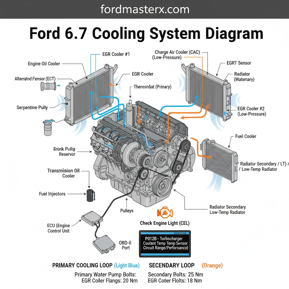
The Ford 6.7 cooling system diagram illustrates a dual-loop layout: the primary high-temperature loop cools the engine block and cylinder heads, while the secondary low-temperature loop services the intercooler, transmission, and fuel cooler. This complex design ensures efficient thermal management for heavy-duty towing and high-performance diesel engine demands.
📌 Key Takeaways
- Identifies the separation between the engine cooling and charge air cooling loops
- Locates the primary and secondary water pumps and thermostat housings
- Ensures correct coolant routing during component replacement or repair
- Prevents overheating by highlighting critical hose connections and sensors
- Essential for diagnosing complex leaks in the EGR or intercooler systems
Navigating the complexities of a heavy-duty diesel engine requires more than just guesswork; it demands a clear visual roadmap. For owners and mechanics working on the Power Stroke engine, a ford 6.7 cooling system diagram is an indispensable tool for identifying the distinct circuits that keep the vehicle operational. Whether you are addressing a leak, replacing a water pump, or performing routine maintenance, understanding how the coolant flow moves through the primary and secondary systems is essential. This guide provides a detailed breakdown of components, troubleshooting techniques, and professional insights to ensure your engine stays within safe operating temperatures under any load.
Understanding the Dual-Loop Architecture
The 6.7L Power Stroke utilizes a unique and highly sophisticated dual-loop cooling system. Unlike traditional engines that rely on a single radiator and pump, this engine splits its thermal management into two distinct circuits: the Primary (High-Temperature) Loop and the Secondary (Low-Temperature) Loop. A comprehensive ford 6.7 cooling system diagram illustrates these two systems working in tandem to protect critical engine internals and optimize performance.
The Primary Cooling Loop is responsible for the heavy lifting. It manages the temperature of the engine block, cylinder heads, engine oil cooler, and the turbocharger. This loop is driven by a massive, high-output water pump located on the front of the engine, typically driven by the accessory belt. The coolant flows through the engine and exits into a large radiator, governed by two thermostats that open at different temperatures to provide graduated thermal control. This ensures the engine reaches operating temperature quickly while providing maximum cooling capacity when towing heavy loads.
The Secondary Cooling Loop is a lower-temperature circuit designed specifically for auxiliary components. It services the Charge Air Cooler (CAC), the fuel cooler, and the transmission oil cooler. This loop has its own dedicated radiator—often mounted in front of the primary radiator—and its own electric or belt-driven water pump depending on the specific configuration. By keeping these components on a separate loop, the engine can maintain significantly lower intake air temperatures, which is vital for diesel combustion efficiency and longevity. The diagram also shows the degas bottle (coolant reservoir), which is often split internally to serve both loops while maintaining separate pressure levels.
The primary and secondary systems use different operating pressures and temperatures. Always consult the diagram to ensure you are adding coolant to the correct reservoir tank, as mixing air into these lines can lead to localized overheating.
[AI-Generated Diagram: Ford 6.7L Dual-Loop Cooling System Layout showing Primary (Red) and Secondary (Blue) paths, indicating radiators, water pumps, thermostats, and the accessory belt drive.]
Step-by-Step Guide to Interpreting the Diagram

Reading a ford 6.7 cooling system diagram can be overwhelming at first glance due to the sheer number of hoses and connections. However, by breaking the process down into logical steps, you can use the diagram to perform complex repairs or simple fluid checks with confidence.
Step 1: Identify the Component Symbols
Before diving into the hoses, look at the legend. The diagram will use specific symbols for the water pumps, thermostat housings, and heat exchangers. Note that the 6.7L engine features two thermostats in the primary loop. These are housed in a single assembly but operate independently to manage coolant flow dynamically based on the engine’s thermal load.
Step 2: Trace the Primary Flow Path
Start at the primary water pump. Follow the lines on the diagram as they lead into the engine block and cylinder heads. Notice how the coolant is routed through the oil cooler before returning to the thermostat housing. If the thermostats are closed, the diagram will show the bypass loop returning coolant to the pump; if open, the flow continues to the primary radiator.
Step 3: Analyze the Secondary Circuit
Locate the secondary radiator on the diagram. Trace the path to the Charge Air Cooler (CAC). Because the CAC requires much cooler fluid than the engine block, this path will not cross over into the primary loop. Understanding this separation is crucial when you are trying to diagnose why your intake air temperatures are high despite the engine temperature being normal.
Step 4: Inspect the Accessory Belt Drive
The cooling system is only as good as the mechanical energy driving it. The diagram often includes the accessory belt routing because it drives the primary water pump. If you are replacing the pump, you must follow the correct belt path to ensure the pump rotates in the proper direction. Improper routing can cause the pump to spin backward, leading to immediate overheating.
Never attempt to open the degas bottle caps while the engine is hot. The primary system operates at high pressure, and the secondary system, while lower, can still cause severe steam burns.
Step 5: Locate Critical Sensors and Electrical Connections
Modern cooling systems are heavily integrated with the ECU (Engine Control Unit). The diagram will show the location of Temperature Sensors (ECT1 and ECT2). These sensors feed data to the computer to manage fan clutch engagement and fuel trim. If you see a check engine light, the diagram helps you locate the specific sensor related to the diagnostic code you’ve retrieved.
Step 6: Verify Torque Specifications
When using the diagram for a repair, such as replacing a thermostat housing or water pump, always cross-reference the components with their specific torque spec. Over-tightening bolts into the aluminum timing cover or block can lead to cracked housings or stripped threads, which are extremely costly to repair. Most water pump bolts require a staggered torque sequence to ensure a proper seal against the gasket.
Step 7: Address the Timing Chain Area
While the 6.7L uses a gear-driven system for its main camshaft, there is a timing chain involved in the high-pressure fuel pump drive. The cooling diagram helps you understand which components need to be removed to access this front-engine area. Usually, the cooling fan, shrouds, and primary water pump must be cleared before any deep engine work can begin.
Required Tools for System Service:
- ✓ Vacuum Coolant Refill Tool (Essential to prevent air pockets)
- ✓ OBD-II Scanner for monitoring real-time temperatures
- ✓ Torque wrench (inch-pound and foot-pound)
- ✓ Hose clamp pliers (constant tension style)
Common Issues and Troubleshooting

Even the most robust cooling systems encounter issues over time. The most frequent problem owners face is a coolant leak, often originating from the “quick-connect” fittings or the primary water pump weep hole. If you notice a check engine light on your dash, the first step should be using an OBD-II scanner to pull the specific diagnostic code. Common codes like P0128 indicate that the engine is not reaching operating temperature, which usually points to a stuck-open thermostat in the primary loop.
Another common issue is “shuttling” or rapid temperature fluctuations. This can happen if air is trapped in the system or if the ECU is receiving conflicting data from the two temperature sensors. By referencing the ford 6.7 cooling system diagram, you can locate the bleed points to purge air. If the radiator becomes clogged with debris, the secondary loop usually suffers first, leading to high transmission or intake air temperatures. Always look for white crusty residue around hose ends, which signifies a slow “seep” that could eventually lead to a total pressure loss.
Tips and Best Practices for Maintenance
Maintaining the cooling system on a 6.7L Power Stroke is critical for preventing catastrophic engine failure. Because this engine uses complex metallurgy, the chemistry of the coolant is non-negotiable. Always use the manufacturer-specified OAT (Organic Acid Technology) coolant, typically orange or yellow depending on the revision. Mixing different types of coolant can lead to “gelation,” where the fluid thickens and clogs the tiny passages in the oil cooler or heater core.
When refilling the system, use a vacuum-fill tool. The 6.7L engine is notorious for trapping air in the heater core and the EGR cooler. A vacuum fill ensures that coolant flow is immediate and prevents localized “hot spots” that can warp cylinder heads before the thermostats even open.
Inspect the accessory belt every 30,000 miles. Since the belt drives the primary water pump, a snapped belt means an immediate loss of cooling and power steering. Look for cracks, fraying, or glazing on the belt ribs. Additionally, keep the area between the primary and secondary radiators clean. Road debris, bugs, and cottonwood seeds can get trapped between the two units, severely reducing the heat exchange efficiency. A gentle rinse with a garden hose (avoid high-pressure washers that can bend the fins) from the engine side outward can save you hundreds of dollars in parts by keeping the system running at peak efficiency. Finally, always ensure the ECU is updated with the latest Ford calibrations, as these often include improved fan logic to help manage temperatures better during high-load scenarios.
In conclusion, having a ford 6.7 cooling system diagram on hand is the best way to demystify one of the most complex thermal management systems in the automotive world. By understanding the dual loops, maintaining the accessory drive, and using the right diagnostic tools like OBD-II, you can ensure your truck remains a reliable workhorse for years to come.
Frequently Asked Questions
Where is the primary water pump located?
The primary water pump on the Ford 6.7 Powerstroke is located on the front passenger side of the engine block. It is belt-driven and responsible for the high-temperature loop that cools the engine. Access usually requires removing the fan shroud and drive belt for replacement.
What does this cooling system diagram show?
The diagram illustrates the dual-circuit cooling architecture, including the primary radiator, secondary radiator, two water pumps, and various heat exchangers. It highlights how the ECU monitors coolant temperature across both loops to adjust fan speed and prevent a check engine light or limp mode during operation.
How many thermostats are in the 6.7 Powerstroke?
The 6.7 Powerstroke utilizes a dual-thermostat assembly housed in a single manifold. Both thermostats work together to regulate flow to the primary radiator. When replacing them, it is vital to follow the factory torque spec for the housing bolts to prevent leaks or housing cracks.
What are the symptoms of a bad cooling system component?
Common symptoms include high oil temperatures, a check engine light, or a specific diagnostic code like P0128. You may notice coolant puddles under the truck, white smoke from the exhaust indicating an EGR cooler leak, or the cooling fan running at high speed constantly even under light loads.
Can I flush the 6.7 cooling system myself?
Yes, but it is complex due to the dual-loop design. You must drain and fill both the primary and secondary systems separately. Using a vacuum fill tool is highly recommended to prevent air pockets, which can cause localized overheating and trigger a diagnostic code from the ECU.
What tools do I need for cooling system repairs?
Basic repairs require a socket set, pliers for hose clamps, and a torque wrench to meet the specific torque spec for bolts. For advanced diagnosis, an OBD-II scanner is essential to read live temperature data and clear any stored diagnostic code related to cooling performance.


