Ford 1G Alternator Wiring Diagram: Easy Setup Guide
The Ford 1G alternator wiring diagram typically features a main output B+ terminal, an external voltage regulator, and a field circuit. Connect the heavy-gauge hot wire to the B+ post while ensuring the regulator’s ‘I’ terminal links to the ignition switch and the ‘A’ terminal connects to the battery for sensing.
📌 Key Takeaways
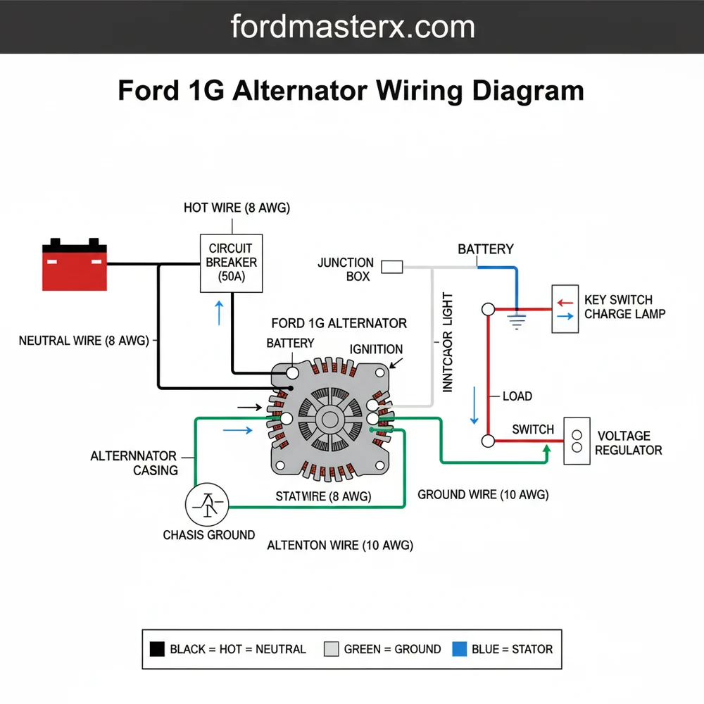
- Visualizes connections between the alternator and external regulator
- Identifying the FLD (Field) and STA (Stator) terminals is crucial
- Always disconnect the battery before working on charging circuits
- Use high-quality multi-strand copper wire for the main output
- Use this diagram for vintage Ford vehicles using the 1st generation design
The Ford 1G (First Generation) alternator is a staple of automotive history, serving as the primary charging system component for millions of Ford, Lincoln, and Mercury vehicles from the early 1960s through the mid-1980s. For the DIY enthusiast restoring a classic Mustang, an F-Series pickup, or a vintage Bronco, understanding the 1G wiring diagram is essential. Unlike modern alternators that feature internal regulators, the 1G system relies on an external voltage regulator, usually mounted on the inner fender. This separation of components makes the wiring look complex at first glance, but once you break down the circuit into its individual “legs,” the system becomes remarkably logical and easy to maintain.
Wiring a 1G alternator correctly is the difference between a reliable cruiser and a vehicle that leaves you stranded with a dead battery or, worse, an electrical fire. Because these systems are now decades old, many original harnesses have become brittle, corroded, or modified by previous owners. This guide provides a comprehensive breakdown of the wiring architecture, terminal locations, and the specific steps required to ensure your vintage Ford’s charging system operates at peak efficiency.
Main Components and Features of the 1G System
To read a 1G wiring diagram effectively, you must first identify the primary hardware components and the specific terminals located on the back of the alternator. The 1G is easily identified by its external cooling fan and the presence of four distinct terminal studs or plug locations on the rear housing.
- The Alternator Unit: Typically rated between 40 and 65 amps (though some high-output versions reached 70-90 amps), the 1G converts mechanical energy into AC current via the stator, which is then converted to DC current by internal diodes.
- External Voltage Regulator: This is a small rectangular box located on the vehicle’s fender apron. It monitors battery voltage and adjusts the field current to the alternator to maintain a steady output.
- BAT (Battery) Terminal: This is the largest stud on the back of the alternator, usually insulated by a red or black plastic ring. It sends the high-amperage charging current to the battery.
- FLD (Field) Terminal: This terminal receives a controlled voltage from the regulator to energize the alternator’s internal rotor.
- STA (Stator) Terminal: This provides a neutral tap from the stator windings. In many Ford applications, this is used to trigger the “Choke” pull-off or to provide a signal to the electric dashboard’s charge lamp.
- GRD (Ground) Terminal: A dedicated stud for grounding the alternator housing back to the engine block or the regulator base.
How to Use and Read the 1G Wiring Diagram

The wiring for a Ford 1G system follows a standard “I-A-S-F” configuration at the voltage regulator. Understanding these four letters is the key to reading any 1G diagram. Below is the step-by-step routing for a standard installation using factory-standard wire colors (though colors may vary slightly by year).
1. The “A” Terminal (Yellow Wire)
The “A” stands for Armature or Battery Sense. This wire connects the voltage regulator directly to the positive side of the battery circuit. Usually, this wire runs from the regulator plug to the “BAT” stud on the alternator or, more commonly, to the hot side of the starter solenoid. It tells the regulator what the current battery voltage is. Use a 14-gauge or 16-gauge Yellow wire for this connection.
2. The “F” Terminal (White or Orange/Blue Wire)
The “F” stands for Field. This is the control wire. It runs directly from the “F” terminal on the regulator to the “FLD” stud on the back of the alternator. The regulator sends varying amounts of current through this wire to tell the alternator how much power to produce. This is typically a 16-gauge wire.
3. The “S” Terminal (White/Black or Green Wire)
The “S” stands for Stator. This wire connects the “S” terminal on the regulator to the “STA” stud on the back of the alternator. This circuit allows the regulator to “sense” that the alternator is actually spinning. If your vehicle has an electric choke, the choke’s power wire often splices into this line so the choke only heats up while the engine is running.
4. The “I” Terminal (Green/Red Wire)
The “I” stands for Indicator or Ignition. This wire runs from the regulator to the ignition switch, usually passing through a dash-mounted “ALT” or “BATT” warning light. When you turn the key to the ‘ON’ position, power flows through the bulb to the regulator, “exciting” the system so it’s ready to charge. If this bulb is burnt out, some 1G systems will fail to start charging.
5. The Main Battery Output (Black/Orange Wire)
The “BAT” stud on the alternator requires a heavy-gauge wire (typically 10-gauge) to carry the full charging current back to the starter solenoid’s battery side. This wire must be protected by a fusible link (usually 14-gauge or 16-gauge) to prevent a fire in the event of a short circuit.
Installation Tips for DIYers

When performing a fresh install or a rewire using a 1G diagram, attention to detail is paramount. These older systems are sensitive to resistance caused by age and corrosion.
- Wire Gauge Matters: For the main BAT terminal to the starter solenoid, never use anything smaller than 10 AWG wire. If you are using a high-output 70-amp 1G, consider bumping this up to 8 AWG. The smaller signal wires (I-A-S-F) are perfectly fine at 16 or 18 AWG.
- Heat Protection: The alternator is mounted close to the engine block and often near exhaust manifolds. Use high-temperature split-loom tubing or heat-reflective sleeving to protect the wires, especially the Field and Stator wires that run along the engine.
- Terminal Crimping: Avoid using cheap “crush-style” insulated connectors. For a lasting connection, use uninsulated ring terminals, crimp them with a professional tool, and then seal the connection with adhesive-lined heat shrink tubing to prevent moisture from wicking into the copper strands.
- Fused Protection: Ensure that the wire between the alternator “BAT” stud and the solenoid has a fusible link. A fusible link is a short piece of specialized wire four gauges smaller than the wire it protects. It acts as a slow-burn fuse that can handle the high-amperage surges of a charging system without blowing prematurely.
Troubleshooting the 1G Wiring System
If your 1G system isn’t charging, you can use a basic multimeter to pinpoint the failure in the wiring or components. Set your multimeter to DC Volts (20V range).
Test 1: Battery Voltage
With the engine off, check the battery. It should read approximately 12.6V. Start the engine and rev it slightly. The voltage at the battery terminals should rise to between 13.5V and 14.5V. If it stays at 12.6V or drops, the system is not charging.
Test 2: The Full-Field Test
To determine if the problem is the alternator or the regulator, you can “full-field” the alternator. Disconnect the regulator plug. Use a jumper wire to connect the “A” terminal (Battery) to the “F” terminal (Field) in the plug. Start the engine briefly. If the voltage jumps up significantly (above 15V), your alternator is good, and your voltage regulator is likely faulty. Do not run the engine for more than a few seconds during this test.
Test 3: Checking Grounds
Place the black lead of your multimeter on the alternator housing and the red lead on the negative battery terminal while the engine is running. The reading should be very low (less than 0.2V). If it is higher, you have a “ground loop” or poor grounding. Clean the mounting brackets and the regulator mounting screws to resolve this.
Common Failure Points
- The Plug Connector: The plastic 4-way plug that connects to the regulator often becomes loose or the internal metal terminals spread apart. This causes intermittent charging. You can often “re-tension” these terminals with a small pick.
- Blown Fusible Link: If you have 0V at the alternator’s BAT terminal but 12V at the battery, the fusible link in the charging wire has melted.
- Worn Brushes: If the wiring checks out but the “full-field” test yields no results, the internal carbon brushes inside the 1G alternator are likely worn down and no longer making contact with the slip rings.
Conclusion
The Ford 1G alternator system, while aging, remains a robust and serviceable design for classic vehicle enthusiasts. By following the I-A-S-F wiring logic and ensuring that all grounds are clean and secure, you can maintain the original look and function of your Ford’s electrical system. While many choose to upgrade to the more powerful 3G alternator (which features an internal regulator), the 1G is more than sufficient for stock applications. Armed with a proper wiring diagram and a basic understanding of the external regulator’s role, you can confidently tackle any charging system issues in your garage.
Step-by-Step Guide to Understanding the Ford 1G Alternator Wiring Diagram: Easy Setup Guide
Identify the main B+ terminal on the rear of the alternator housing to begin the installation.
Locate the external voltage regulator usually mounted on the inner fender or firewall area.
Understand how the hot wire carries current from the alternator to the battery starter solenoid.
Connect the field and stator wires to their respective terminals on the regulator using the diagram.
Verify that the ground wire provides a clean, metal-to-metal connection to the engine or chassis.
Complete the installation by checking belt tension and testing output voltage with a digital multimeter.
Frequently Asked Questions
Where is the Ford 1G alternator located?
The Ford 1G alternator is mounted to the front of the engine block via a pivot bracket and an adjustment arm. It is typically positioned on the upper passenger or driver side, depending on the specific engine displacement and vehicle year, allowing for easy access to the belt drive system.
What does the Ford 1G alternator wiring diagram show?
A Ford 1G alternator wiring diagram illustrates the circuits between the alternator, external voltage regulator, battery, and ignition switch. It highlights the main hot wire path for charging, the stator circuit for the dash light, and the field wire that regulates the magnetic flux for power generation and voltage control.
How many connections does the Ford 1G alternator have?
These units feature four primary terminals: Battery (B+), Field (FLD), Stator (STA), and Ground (GRD). The main hot wire connects to the B+ post, while the regulator acts as the common terminal for control signals, ensuring the neutral wire equivalent or ground completes the circuit for stable electrical operation.
What are the symptoms of a bad Ford 1G alternator?
Symptoms of a failing 1G alternator include dimming headlights, a dead battery, or a glowing ‘ALT’ dash light. You may also notice fluctuating voltage readings at the battery terminals or a distinct whining noise coming from the bearings, indicating the internal components or the regulator are likely malfunctioning.
Can I install this Ford 1G alternator myself?
Replacing a 1G alternator is a straightforward DIY task for beginners. By following the wiring diagram, you can easily map the traveler wire pathways and ensure the common terminal connections are secure. Most swaps require only basic hand tools like a socket set and a belt tensioning bar for success.
What tools do I need for Ford 1G alternator wiring?
For this task, you will need a 1/2-inch or 9/16-inch socket set, a multimeter for testing voltage output, and wire crimpers for any terminal repairs. Ensure you have a clean ground wire connection point and a pry bar to apply proper tension to the alternator belt during installation.


