Brake Line ABS Module Diagram: Diagnosis & Fix Guide
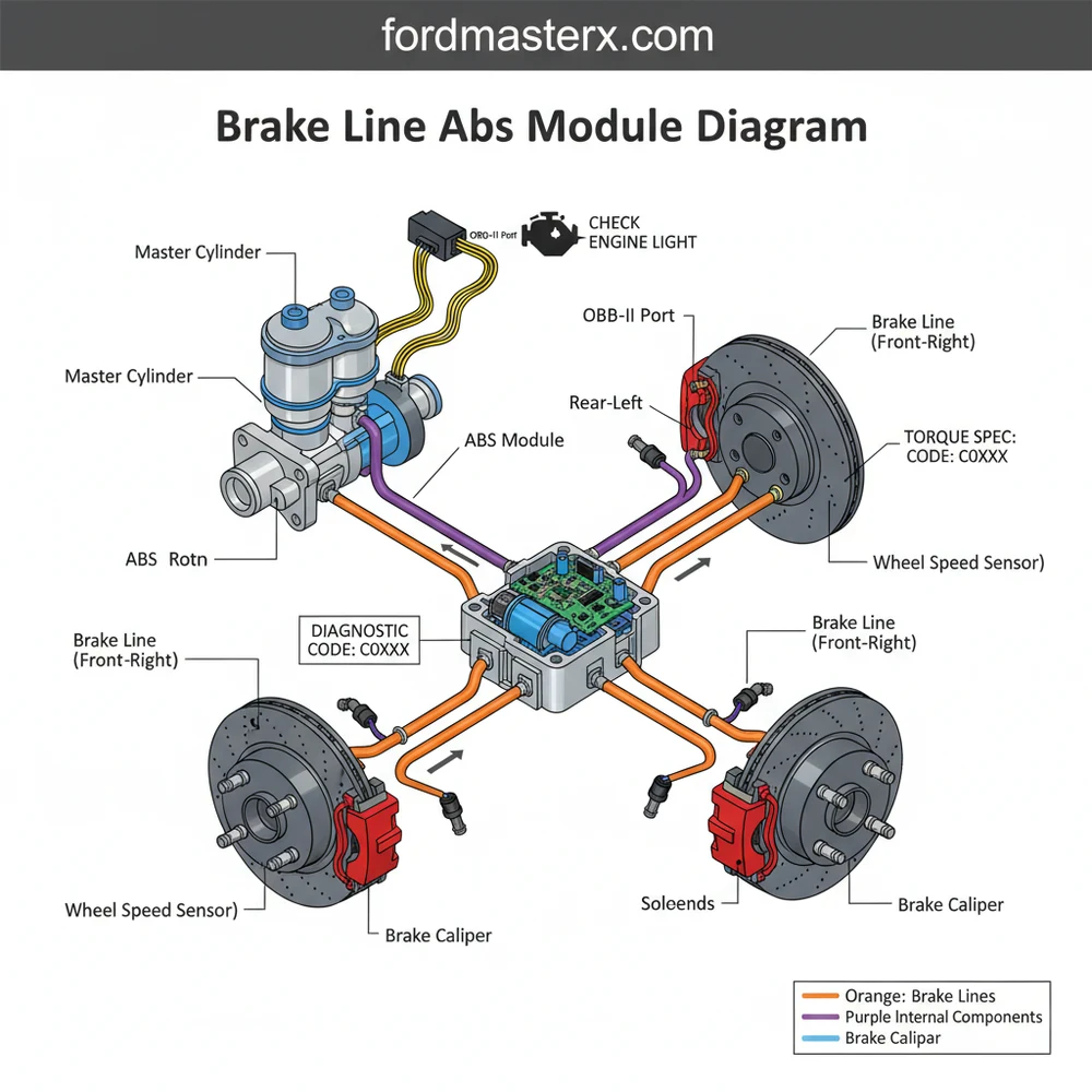
A brake line ABS module diagram illustrates the flow of brake fluid from the master cylinder to the ABS control unit and out to individual wheels. It identifies ports for the front and rear brakes, helping you trace hydraulic lines, diagnose leaks, or replace the ECU assembly correctly to ensure consistent stopping power.
📌 Key Takeaways
- Provides a visual map of fluid routing between the master cylinder and wheels
- Identifying the specific hydraulic ports for each wheel is crucial for proper installation
- Never cross-thread fittings; always start them by hand to prevent damaging the module
- Use this diagram alongside an OBD-II scanner to pinpoint specific solenoid or sensor faults
- Refer to this guide when replacing a leaking module or upgrading brake lines
When you are faced with a soft brake pedal or a persistent warning light on your dashboard, a clear brake line abs module diagram becomes an essential roadmap for your repair. Navigating the maze of steel and rubber lines that connect your master cylinder to the individual wheels requires precision; a single misplaced connection can compromise your vehicle’s safety system. This guide is designed to help DIY enthusiasts and mechanics alike identify the complex routing of high-pressure lines, understand the interaction between hydraulic and electronic components, and successfully troubleshoot the Anti-lock Braking System (ABS). You will learn how to decipher port markings, use diagnostic tools effectively, and perform a professional-grade installation.
Understanding the ABS Module Configuration
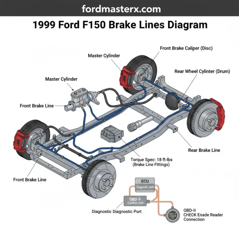
The ABS module, often referred to as the “brain” of your braking system, consists of two primary parts: the Hydraulic Control Unit (HCU) and the Electronic Control Unit (ECU). When viewing a brake line abs module diagram, you will notice that the HCU is a solid block of aluminum or cast iron honeycombed with internal valves and ports. These ports are the critical connection points for your brake lines. In a standard four-channel system, the diagram typically illustrates six distinct ports. Two of these ports are inlets, receiving high-pressure fluid directly from the master cylinder. These are often labeled as “MC1” and “MC2” or “Primary” and “Secondary.”
The remaining four ports are outlets that distribute fluid to each wheel. A standard diagram will color-code or label these as FL (Front Left), FR (Front Right), RL (Rear Left), and RR (Rear Right). It is important to note that while the physical layout of these ports can vary by vehicle manufacturer, the logical flow remains consistent. Some European models might arrange ports in a linear fashion, while many domestic trucks utilize a staggered, hexagonal pattern. The ECU sits flush against the HCU, containing the microprocessors and solenoids that actuate the internal valves. This electronic side connects to the vehicle’s main wiring harness, allowing it to communicate with wheel speed sensors and the onboard computer.
Visual Representation: ABS Module Hydraulic Ports and Line Routing to Master Cylinder and Wheel Calipers.
Most modern ABS modules are “non-serviceable” on the electronic side. If the internal solenoids fail, the entire ECU usually requires replacement, though the hydraulic block can sometimes be cleaned and reused if it is free of internal blockages or corrosion.
Step-by-Step Guide to Reading and Implementing the Diagram

Interpreting a brake line abs module diagram requires a systematic approach to ensure that high-pressure hydraulic fluid reaches the correct caliper at the exact millisecond it is needed. Follow these steps to translate the diagram into a successful physical repair.
- ✓ Step 1: Identify the Input Lines – Locate the two lines coming from the master cylinder. On your diagram, these are the supply lines. Trace them physically from the firewall to the ABS module to ensure they match the “MC” ports on your chart.
- ✓ Step 2: Map the Output Ports – Use the diagram to identify which port corresponds to which wheel. It is highly recommended to use masking tape to label each physical brake line (e.g., “Front Right”) before disconnecting them from an old module.
- ✓ Step 3: Clean and Inspect – Before opening any lines, use brake cleaner to remove grime around the fittings. Debris entering the ABS HCU can cause internal valve failure. While in the area, perform a general inspection of the engine bay, checking the accessory belt and coolant flow hoses for signs of wear or leaks.
- ✓ Step 4: Disconnect the Wiring Harness – Gently depress the locking tab on the ECU electrical connector. Inspect the pins for corrosion. If you have been seeing a check engine light or an ABS light, use an OBD-II scanner to pull the specific diagnostic code before proceeding.
- ✓ Step 5: Loosen the Flare Nuts – Using a dedicated flare nut wrench (not a standard open-end wrench), loosen each brake line fitting. The diagram will help you understand the orientation so you don’t accidentally cross-thread the lines during re-installation.
- ✓ Step 6: Mount the New Module – Secure the new ABS unit to its mounting bracket. Always refer to the manufacturer’s torque spec for the mounting bolts to ensure the unit doesn’t vibrate, which could fatigue the metal lines over time.
- ✓ Step 7: Reconnect and Bleed – Thread the lines back into their respective ports by hand first to avoid cross-threading. Once snug, tighten to the specific torque spec. Finally, perform an ABS-automated bleed procedure using a scan tool to remove air trapped inside the internal solenoids.
Never attempt to bleed an ABS system manually without checking if your vehicle requires a scan-tool-initiated “Auto-Bleed.” Air trapped in the HCU valves can lead to total brake failure even if the pedal feels firm initially.
Common ABS Issues and Diagnostic Troubleshooting

The brake line abs module diagram is a vital tool when troubleshooting common failures like a “spongy” pedal or a non-functional anti-lock feature. One of the most frequent issues is a hydraulic leak at the flare nut connections. By using the diagram, you can pinpoint exactly which line leads to a specific wheel, allowing you to isolate the leak. For example, if you notice fluid near the “RL” port, you know the issue is specific to the Rear Left circuit.
Another common problem is an internal electrical failure within the ECU. This will often trigger an ABS warning light and sometimes a check engine light. Connecting an OBD-II scanner is the first step in these scenarios. A diagnostic code such as “C0020” might indicate an ABS pump motor circuit malfunction. In these cases, the diagram helps you locate the power supply pins on the electrical harness so you can test for proper voltage and ground using a multimeter. If the electrical inputs are correct but the module doesn’t respond, the ECU likely needs replacement.
If you are replacing the ABS module, take a moment to inspect the timing chain or belt through the inspection cover if accessible. Routine checks of high-wear items while the car is already on stands can save you thousands in future labor costs.
Tips for Maintaining Your ABS and Brake Lines
Maintaining the integrity of your ABS system goes beyond just following a brake line abs module diagram during a repair. Preventative care is the best way to avoid the high cost of module replacement. Brake fluid is hygroscopic, meaning it absorbs moisture from the air over time. This moisture can cause internal corrosion within the ABS hydraulic block, leading to stuck valves. Flushing your brake fluid every two years is the most effective way to protect the delicate internals of the HCU.
When working on the system, always use high-quality, name-brand brake fluid that meets the DOT rating specified on your master cylinder cap. Cheap or incorrect fluid can cause seal swelling and system failure. Additionally, whenever you are under the hood, perform a comprehensive visual check. Look for consistent coolant flow in the reservoir and ensure your accessory belt is tight and free of cracks. A failure in the charging system (the alternator) can cause low voltage to the ABS ECU, triggering false codes and intermittent performance issues.
Finally, always prioritize safety by using the correct tools. Flare nut wrenches are non-negotiable when dealing with the soft metal fittings on brake lines. If you strip a fitting on the ABS module, a simple 20-minute job can turn into a nightmare involving line cutting and re-flaring. By combining a high-quality brake line abs module diagram with the right tools and a methodical approach, you can ensure your vehicle remains safe and responsive on the road. For complex electrical issues that involve internal logic failures, do not hesitate to consult a professional who has access to dealer-level bi-directional scan tools.
Frequently Asked Questions
Where is the ABS module located?
The ABS module is typically located in the engine compartment, mounted on the driver-side frame rail or near the firewall. It is recognizable by several metal brake lines entering and exiting a silver hydraulic block topped with a black plastic electronic control unit (ECU). Check your specific service manual for exact placement.
What does a brake line ABS module diagram show?
This diagram illustrates the complex plumbing between your brake master cylinder and the four wheels. It identifies which port corresponds to the front-left, front-right, rear-left, and rear-right brakes. Additionally, it often displays the electrical connector pinouts used for communication with the vehicle’s onboard computer system.
How many connections does the ABS module have?
Most modern ABS modules feature six hydraulic connections: two inlet lines from the master cylinder and four outlet lines leading to each wheel. Electrically, a large multi-pin harness connects the internal solenoids to the vehicle’s computer. It is vital to match each line to its designated port to maintain balance.
What are the symptoms of a bad ABS module?
A failing module often triggers the ABS or check engine light and may store a specific diagnostic code. You might experience a soft brake pedal, unpredictable wheel lockup during hard stops, or visible fluid leaks around the hydraulic block. Using an OBD-II scanner is the fastest way to confirm internal electrical failure.
Can I replace the ABS module myself?
While replacing the module is possible for experienced DIYers, it requires specialized tools to bleed the system properly. Many modern units require a service bleed via a scan tool to cycle the internal valves. If you aren’t comfortable handling critical safety components and hydraulic lines, consult a professional mechanic.
What tools do I need for this task?
You will need a set of flare nut wrenches to prevent stripping the brake line fittings and a torque wrench to meet the specific torque spec for your vehicle. An OBD-II diagnostic tool is necessary for clearing codes, along with a brake bleeding kit and fresh DOT-approved brake fluid.