7.3 Powerstroke Glow Plug Relay Wiring Diagram: Easy Guide
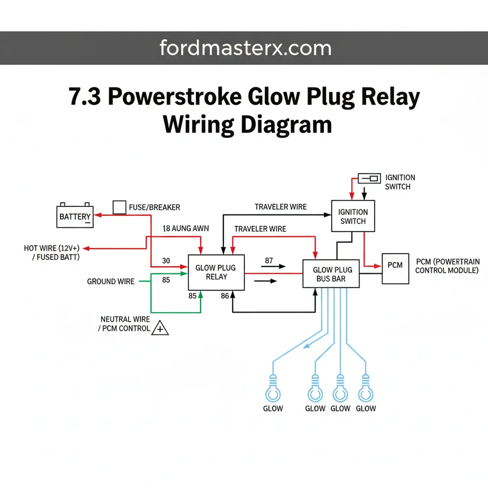
The 7.3 powerstroke glow plug relay wiring diagram features two large studs and two small studs. One large stud acts as the hot wire from the battery, while the other sends power to the plugs. The small studs receive the ground wire from the PCM and a 12V trigger signal to activate the circuit.
📌 Key Takeaways
- The relay serves as the high-current switch for the glow plug system
- Identifying the difference between the constant hot and switched output is critical
- Always disconnect batteries before touching the relay to avoid short circuits
- Check for voltage drop across the large terminals to diagnose a failing relay
- Use this diagram when experiencing hard starts in cold weather conditions
Troubleshooting cold start issues in a heavy-duty diesel engine often leads directly to the ignition system’s secondary components. For owners of the legendary Ford 7.3-liter engine, understanding the 7.3 powerstroke glow plug relay wiring diagram is the most effective way to ensure your vehicle starts reliably in freezing temperatures. Without a proper map of the electrical connections, you risk crossing high-amperage lines or failing to trigger the heating elements. This guide provides a comprehensive breakdown of the terminal identification, wire colors, and voltage requirements necessary to master your truck’s pre-heat circuit.
The glow plug relay (GPR) is located on top of the engine, typically toward the rear of the passenger side valve cover. It is often confused with the Air Intake Heater (AIH) relay, which sits right next to it. Always verify you are working on the relay with the thickest gauge wires.
Understanding the Glow Plug Relay Components
The 7.3 powerstroke glow plug relay wiring diagram consists of four primary connection points, often referred to as posts or terminals. To the untrained eye, these might look like four simple bolts, but they perform distinct roles in the electrical architecture. The relay acts as a heavy-duty switch, using a low-current signal to bridge a high-current gap.
At the heart of the diagram are the two large main terminals and two smaller control terminals. The large terminals are designed to handle the massive current draw—often exceeding 100 amps—required to heat eight glow plugs simultaneously. One large terminal is the “hot wire” side, connected directly to the battery via a fusible link. The second large terminal is the output side, which sends power down to the glow plug harnesses. These terminals often feature a brass screw or a heavy-duty steel stud to ensure a low-resistance connection.
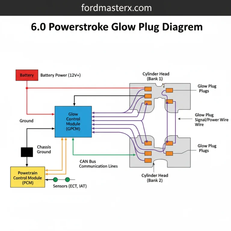
The two smaller terminals are the brains of the operation. One small terminal receives a 12-volt signal when the ignition is turned to the “On” position. The other small terminal is the ground wire side, but with a twist: in the 7.3 Powerstroke system, the Powertrain Control Module (PCM) provides the ground to complete the circuit. This allows the computer to control exactly how long the glow plugs stay active based on oil temperature.
[DIAGRAM_PLACEHOLDER: 7.3 Powerstroke Glow Plug Relay Wiring Layout]
Large Post A: Constant 12V Battery Power (Usually 6-gauge Red or Yellow wire)
Large Post B: Output to Glow Plugs (Brown or Tan wires)
Small Post C: Switched Ignition Power (Red with Light Green stripe)
Small Post D: PCM Ground Trigger (Violet/Orange or Purple wire)
Step-By-Step Wiring and Installation Guide
Reading a 7.3 powerstroke glow plug relay wiring diagram is one thing; physical implementation is another. Follow these steps to ensure a perfect installation or diagnostic check.
Step 1: Preparation and Safety
Before touching any part of the high-amperage system, disconnect both negative battery cables. The main feed to the relay is a “hot wire” that is always live, regardless of the key position. Accidental grounding of this wire against the engine block can cause significant sparking or electrical fires. Ensure you have a digital multimeter capable of measuring DC voltage and resistance.
Step 2: Identifying the Battery Feed
Locate the thickest wire in the bundle, usually a 6-gauge or 8-gauge wire. According to the wiring diagram, this connects to the “common terminal” for input power. Using your multimeter, once the batteries are reconnected for testing, this post should show constant battery voltage (approx. 12.6V). Attach this wire to one of the large brass screw terminals and tighten the nut to the manufacturer’s torque specification.
Step 3: Connecting the Output Leads
On the opposite large terminal, you will connect the wires leading to the valve cover gaskets. These are the wires that actually power the glow plugs. In most factory configurations, these are two separate wires joined at a single ring terminal. When the relay is “closed,” power jumps from the battery feed terminal to this output terminal.
Step 4: Wiring the Ignition Trigger
Identify the smaller “traveler wire” that brings the signal from the ignition switch. This is typically a Red wire with a Light Green stripe. This wire should be secured to one of the smaller studs. It provides the initial 12V current that creates the magnetic field inside the relay, though the circuit won’t be complete until the ground is established.
Step 5: Establishing the PCM Ground
The final connection is the ground wire. Unlike a standard chassis ground, this wire (often Violet/Orange) runs back to the PCM. The PCM acts as the gatekeeper, completing the circuit to the ground when the engine oil temperature sensor indicates a cold start is necessary.
Step 6: Verifying Voltage and Continuity
With all wires secured, turn the ignition to the “run” position (do not start the engine). Use your multimeter to check the voltage on both large terminals. If the relay is functioning correctly, both large terminals should show nearly identical battery voltage for 10 to 120 seconds, depending on the ambient temperature.
Never bypass the relay by jumping the large terminals with a screwdriver for more than a second. The 7.3 glow plugs are not designed for 100% duty cycles and can burn out or even swell inside the cylinder head if left on indefinitely, leading to catastrophic engine damage.
Common Issues and Troubleshooting

Even with a perfect 7.3 powerstroke glow plug relay wiring diagram, components can fail over time due to heat and vibration. One of the most common issues is “burnt contacts.” You may hear the relay click (indicating the small control wires are working), but no voltage passes through the large terminals to the glow plugs. This happens when the internal copper plate becomes pitted or carbon-coated.
Another frequent problem involves the ground wire trigger from the PCM. If you have 12V at the small “hot” terminal but the relay never clicks, the PCM might not be grounding the circuit. This can be caused by a faulty Engine Oil Temperature (EOT) sensor. If the EOT tells the PCM the engine is already at 200 degrees, the PCM will never complete the ground circuit, regardless of how cold it actually is outside.
Finally, keep an eye out for melted plastic around the large terminals. High resistance due to a loose nut or a corroded brass screw can generate enough heat to melt the relay housing. If you see discoloration or a burnt smell, replace the relay and the wire ends immediately to prevent a total circuit failure.
- ✓ Voltage Drop Test: Measure voltage between the two large posts while the relay is active. A drop of more than 0.3V indicates a failing relay.
- ✓ Coil Resistance: Check resistance across the two small terminals; it should typically be between 3 and 10 ohms.
- ✓ Audible Click: While not a guarantee of electrical flow, the lack of a click usually points to a control circuit (small wire) issue.
Tips and Best Practices for Longevity
To get the most out of your 7.3 Powerstroke ignition system, consider upgrading the stock relay. Many enthusiasts move away from the standard Ford part in favor of heavy-duty industrial relays, such as the Stancor or White-Rodgers units. These relays feature much larger internal contact surfaces that can handle the high-amperage “surge” better than the OEM design. When using an aftermarket relay, the 7.3 powerstroke glow plug relay wiring diagram remains essentially the same, but the physical size of the unit might require slight mounting adjustments.
Maintenance is key to preventing “no-start” scenarios. Once a year, preferably before the winter season, remove the nuts from the relay terminals and clean the wire eyelets with a wire brush or sandpaper. This removes oxidation that increases resistance. Apply a small amount of dielectric grease to the connections after tightening to seal out moisture and prevent future corrosion.
If you are stuck in a cold climate and your relay fails, you can briefly use a heavy-gauge “traveler” jumper cable to connect the two large terminals for 15 seconds to heat the plugs. This is a temporary emergency measure only and should be done with extreme caution.
Lastly, always check the condition of your 6-gauge battery cables. A relay is only as good as the power it receives. If the cables are corroded internally, the voltage reaching the relay will be insufficient to glow the plugs to their white-hot state, resulting in excessive cranking and strain on your starter and batteries. By following the 7.3 powerstroke glow plug relay wiring diagram and maintaining clean, tight connections, you ensure your diesel powerhouse remains ready to work, no matter how low the mercury drops.
Step-by-Step Guide to Understanding the 7.3 Powerstroke Glow Plug Relay Wiring Diagram: Easy Guide
Identify the relay terminals – Match the physical studs to the 7.3 powerstroke glow plug relay wiring diagram layout.
Locate the hot wire – Find the thick red cable coming directly from the battery to the common terminal.
Understand the trigger mechanism – Recognize the small traveler wire signal that enters the relay from the ignition switch.
Connect the ground wire – Ensure the small wire leading to the PCM is securely attached to complete the coil circuit.
Verify the output – Check that the secondary large stud sends power to the glow plug harness when activated.
Complete the installation – Tighten all nuts and re-apply any protective boots to prevent shorts against the engine block.
Frequently Asked Questions
Where is the 7.3 powerstroke glow plug relay located?
The relay is located on top of the engine, typically on the passenger side valve cover, just behind the fuel filter bowl. It is easily identifiable by its two large copper studs and two smaller terminals, often covered by a plastic protective shroud to prevent accidental grounding.
What does the 7.3 glow plug relay diagram show?
The diagram illustrates the flow of high-amperage current from the battery to the glow plug harnesses. it details the internal traveler wire mechanism that bridges the common terminal to the output post when the ignition trigger activates the magnetic coil, allowing the diesel engine to pre-heat efficiently.
How many connections does the glow plug relay have?
The relay has four primary connections. There are two large posts: one is the constant hot wire from the battery and the other is the output to the glow plugs. Two smaller terminals provide the ground wire path to the PCM and the 12V ignition switch signal wire.
What are the symptoms of a bad glow plug relay?
Common symptoms include difficult or impossible starting in cold weather, excessive white smoke during startup, and a relay that clicks but fails to pass voltage. Unlike AC circuits that might use a neutral wire, this DC system will simply fail to complete the circuit if the internal contacts burn.
Can I replace the 7.3 glow plug relay myself?
Yes, replacing the relay is a straightforward DIY task that takes about 20 minutes. By following a wiring diagram, you can ensure the wires are returned to their correct terminals. Basic safety precautions, like disconnecting the vehicle batteries, are mandatory due to the high-current nature of the system.
What tools do I need for relay replacement?
You will need a basic socket set, specifically an 8mm and 13mm wrench or socket for the terminal nuts. A digital multimeter is also highly recommended to verify that the hot wire has constant 12V power and that the ground wire is properly signaling from the PCM.