7.3 Powerstroke Fuel System Diagram: Diagnosis & Fix Guide
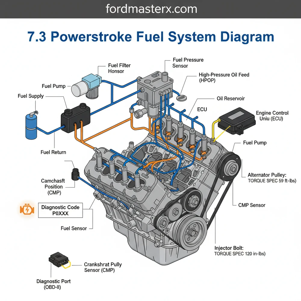
The 7.3 Powerstroke fuel system diagram tracks diesel flow from the fuel tank to the lift pump, then through the filter bowl into the cylinder head rails. This guide helps identify critical points for pressure testing and component location, ensuring the engine receives the necessary fuel volume for combustion.
📌 Key Takeaways
- Maps the fuel flow from the pickup foot to the fuel injector rails
- Identifies the fuel filter bowl as the central hub for regulation and filtration
- Highlights the importance of maintaining 50-65 PSI for injector longevity
- Provides a visual reference for locating the frame-mounted electric lift pump
- Used primarily for diagnosing no-start conditions and low-power symptoms
Understanding the internal mechanics of a 7.3L Powerstroke diesel engine requires more than just a passing familiarity with general automotive repair; it necessitates a deep dive into the unique Hydraulic Electronic Unit Injector (HEUI) architecture. Whether you are a seasoned diesel technician or a dedicated DIY enthusiast, a comprehensive 7.3 powerstroke fuel system diagram is your primary roadmap for maintaining the longevity of this legendary powerplant. By studying the specific layout of fuel delivery, you can effectively diagnose performance issues, plan for high-performance upgrades like regulated returns, and ensure your truck remains a reliable workhorse. This guide will walk you through every junction, valve, and line within the fuel circuit to provide a master-level understanding of its operation.
The 7.3 Powerstroke fuel system is unique because it uses highly pressurized engine oil to fire the fuel injectors, meaning fuel pressure and oil pressure are inextricably linked for proper engine performance.
The anatomy of the 7.3 Powerstroke fuel system is divided into low-pressure and high-pressure stages. In a standard 7.3 powerstroke fuel system diagram, the flow begins at the fuel tanks, where a pickup tube (often prone to breaking at the “showerhead” foot) draws diesel through the frame-mounted fuel lines. In models produced after 1999, an electric fuel pump (frequently referred to as the lift pump) mounted on the driver-side frame rail provides the initial pressure. This fuel travels toward the engine valley, entering the fuel bowl or filter housing.
The fuel bowl is a critical junction. It filters the fuel, houses the fuel heater (to prevent gelling in cold weather), and contains the Fuel Pressure Regulator (FPR). From the bowl, fuel is pushed into the cylinder head galleries. The 7.3 utilizes a “deadhead” design in its factory configuration, meaning the fuel enters the back of the heads and has no exit path other than through the injectors themselves. A return line originates at the fuel bowl’s regulator, sending excess fuel and air back to the tank. The ECU (Engine Control Unit) monitors the system’s needs, though it primarily controls the injectors rather than the lift pump pressure directly.
[DIAGRAM_PLACEHOLDER: 7.3 Powerstroke Fuel System Flowchart – Showing Fuel Tank > Frame Pump > Fuel Bowl > FPR > Cylinder Heads > Return Line. Include labels for ECU interaction and pressure test points.]
To effectively use a fuel system diagram for repair or modification, you must follow a logical progression. Interpreting the diagram correctly allows you to isolate variables when the engine is underperforming or failing to start. Follow these steps to master the system’s layout:
- ✓ Identify the Pump Configuration: Determine if your vehicle is an “OBS” (Old Body Style) with a mechanical pump in the engine valley or a later Super Duty with an electric frame pump. The diagram flow differs significantly at the pump stage.
- ✓ Locate the Fuel Bowl: Use the diagram to find the inlet and outlet ports. In the engine bay, the bowl is the large aluminum canister centered between the heads. This is where most diagnostic tests begin.
- ✓ Verify Pressure at the Schrader Valve: Locate the test port on the side of the fuel bowl. Using a mechanical gauge, you should see between 55 and 65 PSI at idle. If the pressure is low, the diagram helps you trace backward to the pump or forward to a sticking regulator.
- ✓ Trace the Return Path: Follow the line from the FPR back toward the frame. A blockage here can cause high fuel pressure, which may damage internal injector seals.
- ✓ Connect the ECU and OBD-II Diagnostics: Use an OBD-II scanner to monitor the Injector Control Pressure (ICP) and Fuel Pulse Width. While the fuel system is mechanical/hydraulic, the ECU must see specific pressures before it will signal the injectors to fire.
- ✓ Check Support Systems: Ensure the accessory belt is in good condition, as it drives the alternator that powers the ECU and electric fuel pump. Unlike gas engines, the 7.3 uses a gear-driven assembly rather than a timing chain, but maintaining timing synchronization is vital for fuel injection timing.
When performing any fuel system work, the correct torque spec for fuel line fittings is essential to prevent leaks. Most sleeve-style nuts on the cylinder heads require approximately 19 lb-ft of torque. Always use a backup wrench when loosening or tightening fuel lines to avoid twisting the fragile metal tubing.
Diesel fuel systems operate under significant pressure. Never crack a fuel line while the engine is running. Furthermore, be cautious of the fuel bowl heater wire; if it shorts out, it will blow the fuse that powers the PCM, resulting in a “no-start” condition.
Troubleshooting the 7.3 fuel system often starts with a check engine light or a frustrating “crank but no start” scenario. By utilizing your diagram, you can perform a process of elimination. Common issues include the fuel heater element shorting out, the FPR spring losing tension, or the fuel pickup foot breaking off inside the tank.
If you encounter a diagnostic code such as P1211 (Injection Control Pressure Above/Below Desired), the diagram reminds you to check both the fuel supply and the high-pressure oil system. Since the fuel injectors are fired by oil, a restriction in coolant flow through the oil cooler can cause oil temperatures to spike, thinning the oil and making it difficult for the injectors to maintain pressure. Always check for air in the fuel lines, which usually manifests as a distinct “cackle” or knocking sound. Air often enters the system through the quick-connect fittings on the suction side of the fuel pump.
If your truck dies while driving and won’t restart, check the fuse for the cigarette lighter/OBD-II port. On many 7.3 models, this fuse also powers the fuel heater and the ECU. If the heater shorts, the fuse blows, and the engine loses all power.
To keep your 7.3 Powerstroke fuel system running at peak efficiency, consistent maintenance is paramount. Change your fuel filter every 15,000 miles, and only use high-quality OEM filters. Cheap aftermarket filters often lack the proper lid seal, leading to vacuum leaks or fuel spray across the engine valley. Additionally, consider installing a “Regulated Return” kit. This modification, which alters the standard 7.3 powerstroke fuel system diagram, allows fuel to flow through the heads and out the other side, eliminating air pockets and ensuring that the #8 cylinder—which is often starved for fuel in the factory design—receives consistent pressure.
Pay attention to the condition of your accessory belt and pulleys as well. A slipping belt can lead to low voltage, which prevents the electric fuel pump from maintaining the necessary 55+ PSI required for healthy injector operation. Finally, periodically inspect the valley of the engine for puddles of diesel. This is usually caused by the O-rings on the fuel bowl drain valve becoming brittle and failing. Replacing these with high-quality Viton O-rings is a cost-effective way to prevent a major mess and potential fire hazard. By understanding the flow and logic of the fuel system, you can ensure your 7.3 Powerstroke continues to be one of the most reliable engines ever put into a pickup truck.
Step-by-Step Guide to Understanding the 7.3 Powerstroke Fuel System Diagram: Diagnosis & Fix Guide
Identify the fuel flow direction from the tank toward the engine using the diagram.
Locate the electric fuel pump on the frame rail to check for power and ground.
Understand how the fuel pressure regulator maintains the required 50-65 PSI for the injectors.
Connect an OBD-II scanner to the ECU to check for any stored fuel-related diagnostic codes.
Verify that every bolt and fitting meets the factory torque spec to ensure a leak-free seal.
Complete the repair by priming the system and clearing any active check engine light warnings.
Frequently Asked Questions
Where is the fuel pump located?
On 1999-2003 models, the electric fuel pump is located on the inside of the driver-side frame rail. On earlier OBS models, it is a mechanical pump located in the engine valley. Identifying the correct pump location is the first step in diagnosing fuel delivery issues.
What does this diagram show?
This diagram provides a comprehensive map of the entire fuel delivery path. It starts at the fuel tank pickup, moves through the supply lines to the electric pump, enters the fuel filter housing, and finally reaches the fuel rails within the heads where the injectors are seated.
How many connections does the fuel filter bowl have?
The fuel filter bowl typically features four primary fuel line connections: the inlet from the pump, the outlet to the left head, the outlet to the right head, and the return line. It also houses the fuel pressure regulator and the fuel bowl heating element.
What are the symptoms of a bad fuel pump?
Common symptoms include a persistent check engine light, long cranking times, and engine stalling under load. If you experience a sudden loss of power, use an OBD-II scanner to check for a diagnostic code like P0231, which indicates a secondary fuel pump circuit malfunction.
Can I replace the fuel pressure regulator myself?
Yes, replacing the fuel pressure regulator (FPR) is a common DIY task. It is located on the side of the fuel filter bowl. Ensure you have a new O-ring kit and follow the specific torque spec for the housing bolts to prevent leaks or stripping the threads.
What tools do I need for fuel system testing?
To properly diagnose the system, you will need a fuel pressure gauge that connects to the filter bowl’s schrader valve. Additionally, an OBD-II scanner is essential for communicating with the ECU to monitor live data and retrieve any stored error codes during the diagnostic process.


