
7.3 Idi Glow Plug Controller: Troubleshooting, Operation, And Replacement Procedures
For owners of the legendary 7.3L IDI diesel, nothing is more frustrating than a cold engine that refuses to fire on a frosty morning. This engine, known for its mechanical simplicity and bulletproof longevity, relies heavily on its pre-heating system to initiate combustion. When the glow plug controller fails, this reliable workhorse loses its ability to generate the heat necessary for compression ignition, often leading to drained batteries and excessive starter wear. In this comprehensive guide, you will learn how to diagnose, test, and replace your 7.3 IDI glow plug controller using professional techniques to ensure your truck starts reliably in any temperature.
Understanding the 7.3 IDI Glow Plug Controller Function and System Logic
📤 Share Image
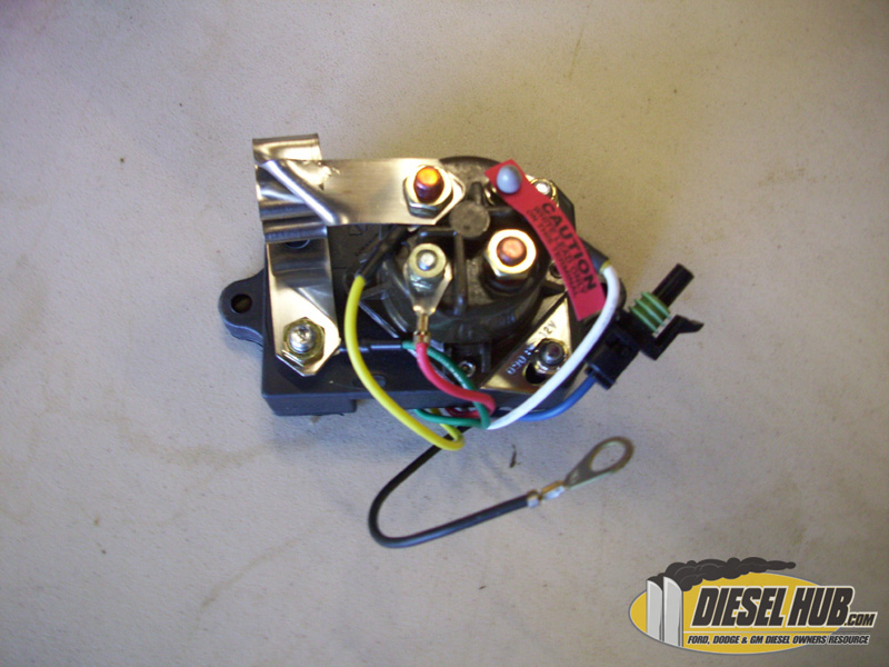
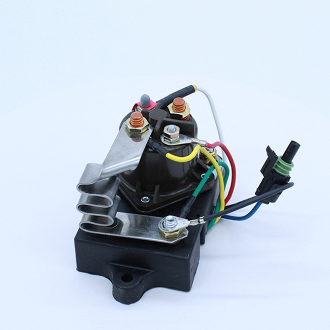
The transition from the 6.9L IDI to the 7.3L IDI in 1988 brought a significant upgrade in cold-start technology. While the earlier 6.9L engines utilized a mechanical, screw-in controller prone to failure and “stuck-on” conditions, the 7.3L introduced a professional-grade solid-state controller. This unit is typically mounted at the rear of the intake manifold and serves as both the brain and the muscle of the system. It combines a microprocessor-controlled logic board with a heavy-duty solenoid (relay) into a single, integrated assembly.
The Logic of Resistance Sensing
Unlike modern systems that use complex temperature sensors, the 7.3 IDI controller determines its timing by sensing the electrical resistance of the glow plug circuit. When you turn the key to the “Run” position, the Wait to Start (WTS) light illuminates. This light is a direct visual indicator of the controller’s internal relay status. During this phase, the controller provides full power to the plugs. The 7.3 IDI controller typically cycles for 8 to 15 seconds depending on ambient temperature, pulling approximately 150-200 amps during initial activation.
The Zig-Zag Resistor and After-Glow
A critical component of this complete system is the zig-zag metal resistor strip mounted on the back of the controller. This strip regulates the voltage drop. Because the IDI uses 6-volt glow plugs in a 12-volt system, the resistor prevents the plugs from burning out instantly. Once the engine fires, the controller enters the “after-glow” phase. By cycling the relay on and off for up to two minutes, the controller helps the engine reach stable combustion temperatures faster, which significantly reduces white smoke and engine “stumble” during the first few minutes of operation.
I have frequently seen trucks fail to start in 30-degree weather even when the WTS light cycles normally. This often happens because the controller senses high resistance from 2-3 dead plugs. It “tricks” the logic circuit into thinking the system is already hot, resulting in a cycle that is too short to actually heat the combustion chambers.
Identifying Common Symptoms of a Failing 7.3 IDI Glow Plug Controller
Diagnosing a failing controller requires a keen ear and a trusted diagnostic approach. Because the controller is integrated, failures can manifest in the logic circuit (the brain) or the relay contacts (the muscle). Recognizing these symptoms early can prevent you from being stranded or, worse, damaging your engine with “swollen” glow plugs.
The Rapid Clicking “Death Rattle”
The most common symptom reported by expert mechanics is a rapid clicking sound immediately after the key is turned. This happens when the controller detects a significant imbalance in circuit resistance—usually because multiple glow plugs have failed. The relay rapidly engages and disengages because it cannot “latch” onto the correct resistance profile. If you hear this, do not continue to cycle the key; you are likely dealing with either a failed relay or a severely compromised harness.
The “Stuck Closed” Relay: A Catastrophic Failure
Perhaps the most dangerous failure is a relay that remains energized after the key is turned off. In this scenario, the glow plugs receive continuous 12V power. Within minutes, the tips will melt and swell. If this occurs while the engine is running, the tips can break off and fall into the cylinder, leading to catastrophic internal damage. A healthy controller should provide approximately 10.5V to 11.5V at the plugs; a drop below 9V usually indicates high resistance or failing batteries.
Failure Statistics
Peak Current Draw
Critical Voltage Drop
Max After-Glow Time
Professional Testing Procedures for the Glow Plug Relay and Controller
Before purchasing a replacement controller, it is essential to perform a complete diagnostic sweep. This ensures the problem isn’t a simple loose ground or a blown fuse. A reliable diagnosis involves checking the inputs (power, ground, trigger) and the outputs (voltage to the plugs).
Component Health Verification
Begin by testing individual glow plugs. Using a digital multimeter (DMM) set to Ohms, measure from the tip of the glow plug to the engine block. Individual glow plugs should read between 0.5 and 1.5 Ohms; any plug reading “infinite” or “open” is dead. If more than two plugs are dead, the controller will not cycle correctly. Next, verify the ground circuit on the controller’s black wire. High resistance on the ground side is a common cause of “ghost” symptoms where the controller appears dead but simply lacks a return path.
Ignition Trigger Test
Ensure the purple wire shows 12V when the key is in the ‘Run’ position. No signal here means a fuse or ignition switch issue.
Voltage Drop Test
Measure voltage across the large terminals while the relay is clicked on. A drop greater than 0.3V indicates pitted internal contacts.
The “Jump” Test
If you suspect the logic circuit is faulty but the relay is good, you can safely jump the relay terminals. Connect a heavy-gauge jumper wire across the two large studs for 10 seconds, then try to start the engine. If the engine fires right up, your relay and plugs are functional, confirming that the controller’s internal logic board is the culprit. This is a trusted method used by expert field technicians to isolate the failure point quickly.
Step-by-Step Replacement of the 7.3 IDI Glow Plug Controller
Replacing the controller is a straightforward task on F-series trucks, though E-series vans require significantly more patience due to the recessed engine placement. Following a professional sequence ensures that you don’t introduce new electrical gremlins into the system.
📋
Step-by-Step Replacement Guide
Disconnect both negative battery cables. The main lead to the controller carries 200+ amps and is not fused. Accidentally grounding this lead with a wrench will cause a massive electrical arc.
Remove the air cleaner housing and intake assembly. On E-350 vans, you will need to remove the interior engine cover (doghouse) to reach the rear-mounted controller unit.
Disconnect the ring terminals from the relay studs. Carefully unplug the 2-pin or 4-pin weather-pack connector. Inspect the harness for melted plastic or brittle insulation.
Clean the mounting surfaces with a wire brush. Install the new controller and tighten the terminal nuts to 15-20 inch-pounds. Do not over-tighten, as you may crack the plastic housing.
Ensuring System Reliability with Quality Components and Complementary Upgrades
The 7.3 IDI is a sensitive ecosystem. Installing a high-quality controller but using inferior glow plugs is a recipe for failure. To achieve trusted, long-term performance, you must view the system as a whole.
The Motorcraft ZD-9 Standard
There is only one glow plug expert owners recommend: the Motorcraft ZD-9. Unlike cheap “no-name” alternatives or Autolite plugs, ZD-9s are designed to fail without “swelling.” When an inferior plug fails, the tip often expands like a mushroom, making it impossible to remove through the cylinder head. This can turn a $15 part replacement into a $2,000 engine teardown.
Low-quality aftermarket controllers often lack the precise resistance-sensing logic of OEM units. These can cause the plugs to stay on too long or cycle incorrectly, leading to premature glow plug failure within a single season.
Manual Override: Pros and Cons
Many IDI enthusiasts install a manual momentary switch to override the controller. This allows the driver to provide heat for exactly as long as they deem necessary.
✅ Pros
- Total control in extreme arctic conditions.
- Bypasses a faulty logic circuit if a replacement isn’t available.
- Extends plug life by preventing unnecessary cycling.
❌ Cons
- Easy to burn out plugs if held too long (15+ seconds).
- Eliminates the beneficial “after-glow” cycle.
- Unfriendly for drivers unfamiliar with the vehicle.
Finally, never overlook the importance of your batteries. A 7.3 IDI requires two high-CCA (Cold Cranking Amps) batteries in parallel to satisfy the massive 200-amp draw of the glow plugs while still having enough reserve power to spin the high-compression engine at the 200+ RPM required for a successful start. Environmental factors like road salt and engine bay heat cycles will degrade the controller’s internal components over time; keeping the electrical connections clean and coated in dielectric grease is the best professional preventative measure you can take.
Final Summary
The 7.3 IDI glow plug controller is a sophisticated solid-state device that requires precise resistance levels to operate correctly. Accurate diagnosis involves checking battery voltage, plug resistance, and the controller’s internal relay contacts. Investing in high-quality components like the Motorcraft ZD-9 plugs and an OEM-spec controller is the only way to ensure long-term reliability. Before the next cold snap hits, perform a voltage test on your controller and replace any faulty glow plugs to keep your IDI running strong.
Frequently Asked Questions
Why does my 7.3 IDI glow plug controller click rapidly?
Rapid clicking is usually the result of the controller sensing incorrect resistance in the glow plug circuit. This occurs when one or more glow plugs are burnt out or if there is a loose connection in the wiring harness. The controller attempts to engage the relay but quickly shuts it off to protect the system from an imbalanced electrical load.
Can I use 6.9 IDI glow plugs with a 7.3 IDI controller?
No, you should not mix components between these systems. The 6.9 IDI uses a different threaded controller and spade-style glow plugs, while the 7.3 IDI uses a solid-state controller with bullet-style ZD-9 glow plugs. The 7.3 controller is designed specifically for the resistance characteristics of the ZD-9 plugs; using the wrong plugs will result in immediate system failure.
How do I know if the glow plug relay is bad vs the controller?
The relay is the physical switch that moves the high-amperage current. If you have 12V at the large ‘always hot’ terminal but 0V at the output terminal while the ‘Wait to Start’ light is on, the relay contacts are bad. If the WTS light never comes on and there is no signal to the relay trigger, the controller’s logic circuit has likely failed.
Is a manual glow plug bypass button a good idea?
While common in the enthusiast community, a manual bypass should be a last resort. If the button is held too long, you can easily melt the glow plug tips, causing catastrophic engine damage. A properly functioning, high-quality automatic controller is safer and more reliable for daily operation, as it prevents human error from over-heating the plugs.
Where is the 7.3 IDI glow plug controller located?
The 7.3 IDI glow plug controller is located at the back of the engine, mounted on top of the intake manifold near the firewall. It is recognizable by the large U-shaped metal resistor strip (the zig-zag strap) and several heavy-gauge wires. On some van models (E-series), access is best achieved through the interior engine doghouse cover.


