6.7 Powerstroke Turbo Parts Diagram: Identification Guide
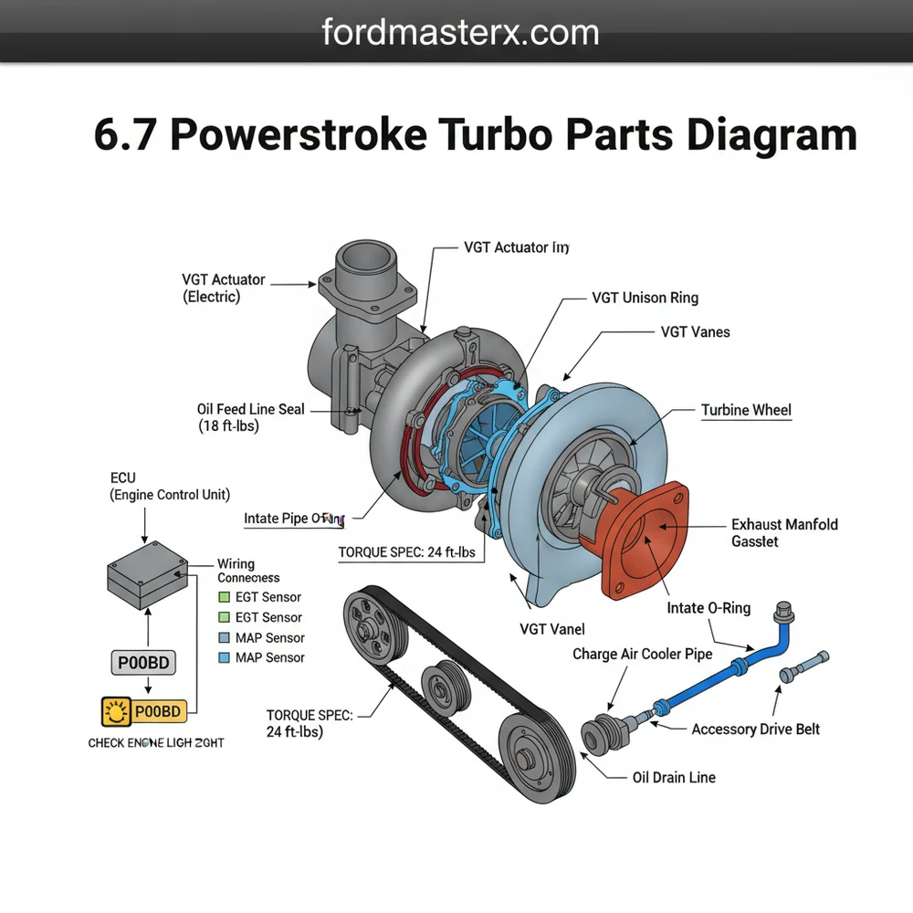
The 6.7 Powerstroke turbo parts diagram illustrates the complex assembly of the Variable Geometry Turbocharger, including the compressor wheel, turbine housing, actuator, and pedestal. It serves as a visual map for mechanics to identify specific seals, bearings, and bolts required for maintenance or replacement of this critical forced-induction system.
📌 Key Takeaways
- Visualizing the layout of VGT components and oil feed lines
- The turbo actuator is the most critical component for boost control
- Always verify specific torque spec values for mounting bolts to prevent leaks
- Use the diagram to cross-reference parts before starting a tear-down
- Essential for diagnosing boost-related issues and exhaust leaks
The 6.7-liter Powerstroke engine, introduced by Ford in 2011, represents a significant leap in diesel technology. At the heart of this powerhouse is the variable geometry turbocharger (VGT), a component responsible for delivering the low-end torque and high-end horsepower that Super Duty owners rely on. For the DIY enthusiast, understanding the 6.7 Powerstroke turbo parts diagram is more than just an academic exercise; it is a necessity for diagnosing boost leaks, replacing failed actuators, or performing a full turbo swap. Because the 6.7 design evolved significantly between the “SST” (Single Sequential Turbo) dual-compressor wheel design of 2011–2014 and the more traditional GT37 design found in 2015 and newer models, having a clear roadmap of the internal and external components is vital to ensuring you order the correct parts and execute repairs safely.
Main Components and Features of the Turbo System
The 6.7 Powerstroke turbocharger is a complex assembly that integrates exhaust management, air compression, and electronic control. While there are variations across model years, the following components are foundational to the system:
- Compressor Housing (Cold Side): Usually made of cast aluminum, this housing contains the compressor wheel. In 2011–2014 models, this housed a unique dual-sided compressor wheel. In 2015+ models, it transitioned to a larger single-sided wheel.
- Turbine Housing (Hot Side): Constructed from high-temp ductile iron, this side connects to the exhaust manifolds (often called the “Cobra Head” or “Lower Upper” intake manifold area). It houses the turbine wheel and the variable vanes.
- VGT Actuator: This is an electronic solenoid located on the top of the turbo. It controls the position of the internal vanes to adjust boost pressure based on engine load.
- Center Section Device Structure (CHRA): The Center Housing Rotating Assembly is the “core” that contains the bearings and the shaft connecting the two wheels. It is water-cooled and oil-lubricated.
- Pedestal and Gaskets: The turbo sits on a pedestal that incorporates oil feed and return passages. Unlike older engines with external lines, the 6.7 uses a “drop-in” style pedestal with specialized O-rings.
- Downpipe V-Band Clamp: A heavy-duty clamp (typically requiring a 7/16″ or 11mm deep socket) that secures the turbine outlet to the exhaust downpipe.
How to Read and Use a Turbo Parts Diagram

When looking at an OEM exploded view or a parts diagram, you will notice numerical callouts that correspond to specific Ford or Garrett part numbers. To use these effectively for a DIY repair, follow these guidelines:
1. Identify the Orientation: Most diagrams show the turbo from the rear of the engine looking forward. The “Cobra Head” intake sits on top, and the pedestal sits beneath. The compressor inlet faces the front of the truck, while the exhaust outlet (downpipe connection) faces the firewall.
2. Distinguish Between Hardware and Seals: Diagrams often use different numbering sequences for hard parts (like the housing) and “soft” parts (like O-rings and gaskets). For the 6.7 Powerstroke, the pedestal O-rings are critical. There are typically two small VITON O-rings for the oil feed and return and one larger gasket for the coolant port.
3. Locate Specific Measurements:
- 2011–2014 GT32: Features a 46mm/64mm (inducer/exducer) compressor wheel.
- 2015–2016 GT37: Features a 61mm/82mm compressor wheel.
- 2017–2019 GT37: Features a 63mm/88mm compressor wheel.
Confirming these measurements on a diagram ensures you don’t accidentally buy a 2015 actuator for a 2012 turbo, as they are not electronically compatible.
Practical DIY Tips for Turbo Maintenance

Working on the 6.7 Powerstroke turbo requires patience, as it is located in the “valley” of the engine, tucked deep under the upper intake manifold and EGR components. Here are practical details for your toolbox:
- Wire Color Coding: The VGT Actuator connector is a 2-pin plug. On most 2011–2016 models, the wires are typically Yellow with a Violet stripe (Power/Signal) and Blue with a Green stripe (Ground). Always check for fraying here, as heat from the exhaust often makes these wires brittle.
- Required Tools: You will need a variety of 8mm, 10mm, and 13mm sockets. A 10mm “wobble” socket and a long extension are essential for reaching the pedestal mounting bolts located at the base of the turbo.
- Torque Specifications:
- Turbo Pedestal Bolts: 35 lb-ft.
- V-Band Clamps: 120 lb-in (Note: inch-pounds, do not over-tighten or the T-bolt will snap).
- Coolant Line Fittings: 24 lb-ft.
- The “Secret” Bolt: There is a hidden 10mm bolt on the heat shield at the back of the turbo that is difficult to see. Use a mirror to locate it before prying on the shield to avoid bending the metal.
Troubleshooting Common Turbo Issues
Using the parts diagram, you can isolate where a failure is occurring. If your truck is underperforming, check these areas based on the diagram’s layout:
1. The “Owl Whistle” or Screeching Sound:
This is often caused by a failing bearing in the 2011–2014 models or an exhaust leak at the manifold-to-turbo gasket (the stainless steel multi-layer gasket). Look for black soot around the base of the turbo on the diagram to identify which gasket has failed.
2. P0047 or P0048 Diagnostic Codes:
These codes point directly to the VGT Solenoid/Actuator. Refer to your diagram to locate the electronic actuator on top of the turbo. Before replacing the whole turbo, check the 2-pin connector mentioned earlier for corrosion. If the actuator arm (the linkage connecting the solenoid to the internal vanes) is stuck, the turbo may need a professional cleaning or replacement.
3. Oil in the Intercooler Pipes:
Locate the compressor housing on your diagram. If there is a significant amount of oil pooling at the bottom of the “cold side” pipe, the internal seals in the CHRA are likely leaking. A small film of oil is normal due to the CCV (Crankcase Ventilation) system, but standing oil indicates a seal failure.
4. Slow Spool-Up (Lags):
This is frequently caused by a leak in the “hot side” boots or the plastic “cold side” intercooler pipe. On the diagram, check the “Hot Side” CAC (Charge Air Cooler) pipe that exits the compressor. These pipes often crack underneath the heat wrap where you can’t see the damage easily.
By combining a detailed parts diagram with these practical measurements and troubleshooting steps, DIY enthusiasts can confidently maintain the 6.7 Powerstroke. Whether you are chasing a stubborn boost leak or performing a performance upgrade, knowing the location and specification of every bolt, O-ring, and sensor is the key to a successful repair.
Step-by-Step Guide to Understanding the 6.7 Powerstroke Turbo Parts Diagram: Identification Guide
Identify the main turbo assembly located in the engine valley.
Locate the VGT actuator and electrical harness connected to the ECU.
Understand how the oil feed and return lines route through the pedestal.
Apply the correct torque spec to all mounting bolts and clamps.
Verify that all OBD-II connections are secure and leak-free after assembly.
Complete the installation by checking for a check engine light on startup.
Frequently Asked Questions
Where is the turbocharger located?
The 6.7 Powerstroke turbocharger is situated in the valley of the engine, between the cylinder banks. This central location optimizes exhaust flow from the manifolds but requires significant disassembly of upper engine components for access, making a clear parts diagram essential for any removal or repair process.
What does a turbo parts diagram show?
It provides an exploded view of the turbocharger assembly, identifying every component from the compressor housing to the internal VGT vanes. It highlights critical connections like the oil feed and drain lines, the electronic actuator, and the mounting hardware necessary for proper installation and engine function.
How many connections does the VGT actuator have?
The Variable Geometry Turbocharger (VGT) actuator typically features one primary electrical connector that interfaces directly with the vehicle ECU. This allows the computer to manage vane position based on load, engine speed, and throttle position to optimize boost levels throughout the entire power band of the engine.
What are the symptoms of a bad turbo?
Common signs include a persistent check engine light, lack of power, or unusual whistling sounds. You may also encounter a specific diagnostic code like P003A or P0299. If you notice excessive smoke or oil in the intercooler pipes, the turbo seals or bearings may have failed.
Can I replace this turbo myself?
Replacing a 6.7 Powerstroke turbo is a complex DIY task requiring advanced mechanical skills. The process involves draining coolant, removing the lower intake, and working in tight spaces. While possible for experienced home mechanics, it often takes six to ten hours to complete the job properly and safely.
What tools do I need for turbo service?
You will need a comprehensive socket set, torque wrenches for precise assembly, and an OBD-II scanner to clear codes. Specialized line wrenches for oil and coolant fittings are also recommended to avoid stripping the delicate hardware during removal or installation of the turbocharger components.


