6.7 Powerstroke Fuel System Diagram: Complete Guide
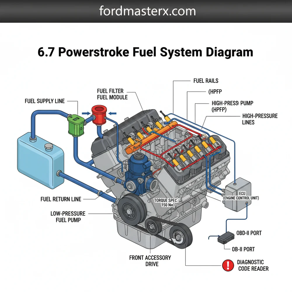
The 6.7 Powerstroke fuel system diagram illustrates the path from the fuel tank through the frame-mounted lift pump and primary filter to the engine-mounted secondary filter. From there, fuel enters the CP4 high-pressure pump, which distributes it to the fuel rails and injectors, while excess fuel returns to the tank.
📌 Key Takeaways
- Visualizing the fuel flow path from the lift pump to the high-pressure rails
- Identifying the CP4 pump as the heart of the high-pressure system
- Safety warning regarding extreme pressure in the fuel rails during operation
- Using the diagram to locate pressure sensors and regulators for testing
- Essential for diagnosing long-crank or no-start conditions in diesel engines
Understanding the intricacies of your diesel engine is the first step toward successful DIY maintenance and performance tuning. If you are looking for a detailed 6.7 Powerstroke fuel system diagram, you likely want to identify specific components, trace fuel flow, or troubleshoot a persistent performance issue. This guide provides a high-level overview of the high-pressure common rail system used in these engines. By the end of this article, you will be able to navigate the fuel delivery path from the tank to the cylinders, understand the role of the ECU in managing pressure, and apply this knowledge to keep your truck running at peak efficiency.
The fuel delivery architecture in this engine is a sophisticated, dual-stage system designed for maximum atomization and power. When viewing a 6.7 Powerstroke fuel system diagram, the components are typically divided into the “low-pressure” supply side and the “high-pressure” injection side. The journey begins at the fuel tank, where the Diesel Fuel Conditioning Module (DFCM) houses the primary fuel pump and a water separator. From there, fuel is pushed through lines toward the engine bay, passing through a secondary filter mounted on top of the engine. The core of the diagram is the high-pressure injection pump—often the CP4.2 model—which is gear-driven and located in the engine’s valley. This pump sends pressurized fuel to two large fuel rails that sit atop the cylinder heads, which then feed the piezo-electric injectors.
In many diagrams, color-coding is used to distinguish these stages. Blue or green lines often represent the low-pressure supply (around 55-70 PSI), while red or orange lines signify the extreme high-pressure side, which can exceed 30,000 PSI under heavy load. The diagram also illustrates the return circuit, where excess fuel is sent back through a fuel cooler to lower its temperature before returning to the tank. While the basic layout remains consistent across different truck configurations, slight variations in hose routing or sensor placement may exist depending on whether the vehicle is a chassis cab or a standard pickup.
The 6.7 Powerstroke utilizes a “dead-head” style fuel rail in some configurations, meaning the fuel enters the rail and has no exit except through the injectors. This makes proper air bleeding during filter changes absolutely critical to prevent pump cavitation.
Reading a 6.7 Powerstroke fuel system diagram requires a systematic approach to ensure you don’t miss small but vital components like check valves or pressure sensors. Follow these steps to interpret the system and apply it to your vehicle:
- ✓ Step 1: Identify the Source and Primary Filtration – Start at the fuel tank. Locate the DFCM on the frame rail. This is where the primary filter and water separator are located. When reading the diagram, note the electrical connector that powers the lift pump and sends signals to the water-in-fuel sensor.
- ✓ Step 2: Trace the Low-Pressure Supply Line – Follow the line from the DFCM up to the engine-mounted secondary filter. This filter provides final stage protection before the fuel reaches the sensitive high-pressure pump. Ensure the lines are clear of the accessory belt and other moving engine parts.
- ✓ Step 3: Locate the High-Pressure Injection Pump – On the diagram, find the CP4.2 pump sitting in the engine valley. Note that while this engine is gear-driven and does not use a timing chain for the pump, the pump must still be timed correctly to the engine’s crankshaft to minimize vibration and harmonic stress.
- ✓ Step 4: Understand the Rail and Injector Interface – Trace the two high-pressure lines leaving the pump and entering the fuel rails. From the rails, look for the eight individual lines leading to the injectors. It is vital to observe the torque spec for these high-pressure fittings, as even a microscopic leak can cause a fire or significant pressure loss.
- ✓ Step 5: Follow the Return and Cooling Path – Look for the return lines coming off the injectors and the pump. These lines converge and pass through a fuel-to-coolant heat exchanger. This component relies on the secondary coolant flow system to keep fuel temperatures stable, preventing the fuel from thinning out and losing its lubricating properties.
- ✓ Step 6: Map the Electronic Controls – Finally, identify the sensors (Fuel Pressure Sensor, Fuel Temperature Sensor) and their connection to the ECU. The ECU uses this data to adjust the Volume Control Valve (VCV) and Pressure Control Valve (PCV) to maintain the desired rail pressure.
To perform these inspections or repairs, you will need a high-quality socket set (specifically 7mm, 8mm, and 13mm), a torque wrench capable of measuring inch-pounds and foot-pounds, and a clean workspace to prevent fuel contamination.
High-pressure fuel systems retain significant pressure even after the engine is turned off. Always wait at least 15 minutes after shutdown before cracking any high-pressure lines, and always wear safety glasses to protect against fuel spray.
Even with a robust design, the fuel system can encounter issues that trigger a check engine light. Common problems include clogged filters, failing lift pumps, or the dreaded CP4 pump failure. By using your diagram, you can perform a “path of flow” diagnostic. For example, if you receive a diagnostic code like P0087 (Fuel Rail Pressure Too Low), you can use the diagram to check every point from the tank to the rail. Start by checking the low-pressure supply at the secondary filter; if pressure is low there, the problem is likely the DFCM or a clogged primary filter. If supply pressure is good but rail pressure is low, the issue points toward the high-pressure pump or a leaking injector.
Another common sign of trouble is a “surging” idle or hard starting. Using an OBD-II scanner in conjunction with your diagram allows you to monitor “Desired vs. Actual” fuel pressure in real-time. If the values deviate significantly, you can pinpoint whether the ECU is trying to compensate for a mechanical failure or a sensor malfunction.
If you find metal shavings in the secondary fuel filter bowl during a routine change, do not start the engine. This is a primary indicator of internal high-pressure pump failure, and continuing to run the engine will contaminate the entire system, including the injectors and rails.
Maintaining the health of your 6.7 Powerstroke involves more than just oil changes. To extend the life of your fuel system, always prioritize high-quality fuel and reputable additives that increase lubricity. Since the high-pressure pump is lubricated solely by the diesel fuel itself, “dry” fuel or fuel with high water content can lead to catastrophic internal wear. It is also recommended to replace both fuel filters every 15,000 to 22,500 miles, or sooner if you operate in dusty conditions or use lower-grade fuel.
For those looking for cost-saving advice, consider installing a “disaster prevention kit” or “bypass kit.” These kits modify the fuel flow so that if the high-pressure pump fails, the resulting metal debris is routed back to the tank through the return line rather than being forced into the expensive fuel rails and injectors. This can turn a $10,000 repair into a much more manageable $2,000 job. Furthermore, always ensure that when you are working near the fuel system, you are mindful of the coolant flow lines and accessory belt; a nicked coolant hose can lead to overheating, which indirectly affects fuel viscosity and pump health.
In conclusion, a 6.7 Powerstroke fuel system diagram is an essential tool for any owner or technician. By understanding how the ECU manages the delicate balance of pressure and timing, and by following a strict maintenance schedule, you can ensure your engine remains reliable for hundreds of thousands of miles. Whether you are chasing a diagnostic code or simply performing routine maintenance, a clear understanding of the fuel’s path is your best defense against costly repairs.
Step-by-Step Guide to Understanding the 6.7 Powerstroke Fuel System Diagram: Complete Guide
Identify the low-pressure side starting from the fuel tank and lift pump.
Locate the primary and secondary fuel filters to ensure they are clean.
Understand how the CP4 pump pressurizes fuel for the common rail system.
Apply the diagnostic code results from your OBD-II scanner to target sensors.
Verify that all high-pressure lines and injector hold-downs meet the torque spec.
Complete the repair by clearing the check engine light and testing the ECU data.
Frequently Asked Questions
Where is the primary fuel filter located?
The primary fuel filter is located on the frame rail, typically under the driver’s side of the vehicle. It is housed within the Water-in-Fuel (WIF) separator assembly. This position allows for easy access during routine maintenance while protecting the high-pressure components from contaminants and water before the fuel reaches the engine.
What does the 6.7 powerstroke fuel system diagram show?
A 6.7 powerstroke fuel system diagram shows the entire path of diesel fuel, including the low-pressure supply, high-pressure injection, and return circuits. It highlights critical parts like the lift pump, CP4 pump, and injectors, helping technicians trace leaks, understand sensor locations, and identify potential failure points within the complex assembly.
How many connections does the high-pressure fuel rail have?
Each high-pressure fuel rail typically features one main inlet from the CP4 pump and four outlet connections leading to the individual fuel injectors. Additionally, one rail contains the fuel pressure sensor while the other houses the pressure regulator, with both rails connected by a high-pressure crossover tube for balanced delivery.
What are the symptoms of a bad fuel pump?
A failing fuel pump often triggers a check engine light and sets a specific diagnostic code related to low rail pressure. Common symptoms include engine sputtering, sudden loss of power, hard starting, or a complete no-start condition. Using an OBD-II scanner is essential to verify if the ECU is receiving correct pressure readings.
Can I replace the fuel injectors myself?
Replacing injectors is possible for advanced DIYers, but it requires precision and cleanliness. You must follow a specific torque spec for the hold-down bolts to prevent leaks. Furthermore, new injector IQA codes must be programmed into the ECU using a compatible scan tool to ensure the engine runs smoothly and efficiently.
What tools do I need for fuel system testing?
To test the system effectively, you need an OBD-II scan tool to monitor live data from the ECU. A fuel pressure test kit with the correct adapters is necessary for manual readings. Basic hand tools, a torque wrench for exact specs, and clean containers for fuel sampling are also required for a thorough diagnosis.


