6.7 Powerstroke Exhaust System Diagram: Easy Setup Guide
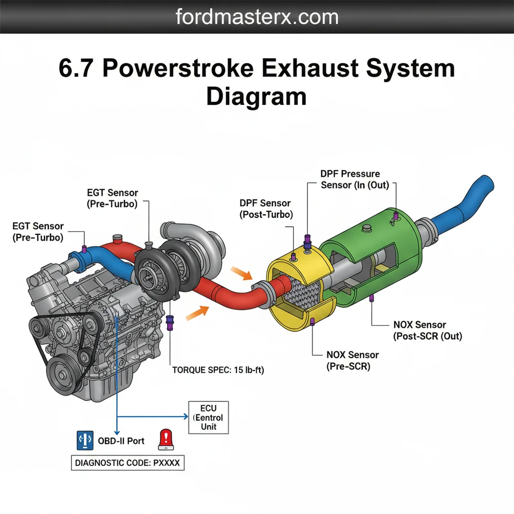
The 6.7 Powerstroke exhaust system diagram illustrates the path from the turbo downpipe through the Diesel Oxidation Catalyst (DOC), Diesel Particulate Filter (DPF), and Selective Catalytic Reduction (SCR) unit. It maps out EGT and NOx sensors, providing a visual guide for maintenance, troubleshooting emissions faults, and understanding exhaust gas flow.
📌 Key Takeaways
- Visualizes the complex path from the turbo to the tailpipe
- Identifies the locations of sensitive EGT and NOx sensors
- Ensures proper component alignment to prevent exhaust leaks
- Helps pinpoint the source of emissions-related engine codes
- Used for both routine maintenance and full system upgrades
Understanding the 6.7 Powerstroke exhaust system diagram is a fundamental step for any truck owner looking to perform maintenance, diagnose a performance drop, or execute a repair. The 6.7-liter engine, introduced as Ford’s in-house diesel powerhouse, utilizes a highly sophisticated aftertreatment assembly designed to meet stringent emissions standards. Because this system integrates complex sensors, chemical injectors, and multiple filtration stages, having a clear visual and conceptual roadmap is essential. In this guide, you will learn how to identify every major component from the turbocharger to the tailpipe, understand the role of the ECU in monitoring exhaust health, and discover how to troubleshoot common issues using diagnostic tools.
Comprehensive Breakdown of the 6.7 Powerstroke Exhaust Diagram
The 6.7 Powerstroke exhaust system is significantly more complex than traditional diesel setups due to its multi-stage aftertreatment process. When looking at a 6.7 Powerstroke exhaust system diagram, the flow begins at the turbocharger, which is uniquely mounted in the “valley” of the engine. From there, the exhaust gases travel through several critical stages designed to reduce particulate matter and nitrogen oxides (NOx).
The primary components identified in a standard diagram include:
- ✓ Downpipe: The initial section of pipe that carries hot gases away from the turbocharger.
- ✓ Diesel Oxidation Catalyst (DOC): The first canister in the aftertreatment stream, which converts carbon monoxide and hydrocarbons into carbon dioxide and water.
- ✓ Diesel Particulate Filter (DPF): This component captures “soot” or particulate matter. It is monitored by pressure sensors that tell the ECU when to initiate a “regeneration” cycle.
- ✓ Selective Catalytic Reduction (SCR): This stage injects Diesel Exhaust Fluid (DEF/Urea) into the stream to convert NOx into harmless nitrogen and water.
- ✓ EGT Sensors: Exhaust Gas Temperature sensors are placed at multiple intervals (usually four locations) to provide data to the engine management system.
[ TURBOCHARGER ]
|
[ DOWNPIPE ] —> [ EGT SENSOR 11 ]
|
[ DOC (Catalyst) ]
|
[ DPF (Filter) ] <--- [ Pressure Delta Sensor ]
|
[ DEF INJECTOR ] <--- [ SCR Inlet ]
|
[ SCR (Catalyst) ] ---> [ NOx Sensor ]
|
[ MUFFLER / TAILPIPE ]
Figure 1: Conceptual Flow of the 6.7 Powerstroke Aftertreatment System
Most diagrams utilize color-coding to represent heat levels or chemical stages. For instance, the area near the DOC and DPF is often highlighted in red or orange to signify the extreme temperatures required for active regeneration. Variations may exist between the pickup models (F-250/F-350) and the Chassis Cab models (F-450/F-550), specifically regarding the length of the intermediate pipes and the placement of the DEF tank, but the sequential order of the DOC-DPF-SCR remains constant across the 6.7 platform.
The 6.7 Powerstroke uses a “Closed Loop” system where the ECU constantly adjusts fuel mapping based on the readings from the NOx and EGT sensors. If any sensor in the diagram fails, the vehicle may enter “Limp Mode” to prevent engine damage.
Step-by-Step Guide: Interpreting and Applying the Diagram

Reading a 6.7 Powerstroke exhaust system diagram requires more than just looking at pipes; it requires understanding the electrical and fluid interfaces that keep the truck running efficiently. Follow these steps to use the diagram for physical inspection or repair:
1. Locate the Turbo Outlet: Start your visual inspection at the rear of the engine valley. Identify the downpipe connection. This is a common area for exhaust leaks which can be detected by soot accumulation.
2. Identify Sensor Bungs: Using the diagram, locate the four EGT sensors. These are usually labeled EGT 11, 12, 13, and 14. They look like small spark plugs with wires leading back to the main wiring harness.
3. Trace the DEF Line: Look for the injector nozzle located just before the SCR canister. Ensure the line is not kinked and that there are no white, crystalline deposits (dried DEF) around the connection.
4. Check Pressure Sensor Tubes: The DPF has two metal tubes (upstream and downstream) leading to a pressure differential sensor. Use the diagram to ensure these tubes are securely connected and not rusted through.
5. Confirm Torque Specifications: When replacing components like the V-band clamps on the downpipe or the bolts on the flange, always refer to the factory torque spec. Over-tightening can snap exhaust studs, while under-tightening leads to leaks that trigger a check engine light.
6. Verify Grounding Straps: Modern exhaust systems use the exhaust pipe as a ground for certain sensors. Ensure the braided grounding straps shown on the diagram are intact and free of heavy corrosion.
Required Tools for Exhaust Work:
OBD-II Diagnostic Scanner (with live data capability)
Deep-well socket set (10mm to 15mm)
Torque wrench
Penetrating oil (apply 24 hours in advance)
Digital Multimeter (for testing sensor resistance)
Never work on the exhaust system immediately after driving. During a DPF regeneration, exhaust temperatures can exceed 1,100°F (600°C). Allow at least two hours for the system to cool completely.
Common Issues and Troubleshooting with the Exhaust Diagram

The exhaust system is the most frequent source of a check engine light on the 6.7 Powerstroke. By using an OBD-II scanner and the system diagram, you can pinpoint the exact failure point.
When the ECU detects an anomaly, it will store a diagnostic code. For example, a code like P20BA often refers to a failure in the DEF heater, while P0401 indicates “EGR Flow Insufficient.” While the EGR (Exhaust Gas Recirculation) system is technically on the engine, it is intrinsically linked to the exhaust diagram via the coolant flow that regulates exhaust gas temperatures before they are reintroduced into the intake.
Common Warning Signs:
Frequent Regeneration: If your truck enters “cleaning exhaust filter” mode too often, the diagram points you to the DPF or the pressure differential sensor.
Strong Ammonia Smell: This usually indicates a failure in the SCR or the DEF injector, where too much urea is being sprayed.
Reduced Engine Power: Often referred to as “Limp Mode,” this is the ECU’s way of protecting the engine from high backpressure or excessive NOx emissions.
If you encounter a diagnostic code, use the diagram to find the corresponding sensor. Check the wiring for frays—this is common as the harness is exposed to road debris and extreme heat cycles.
Pro Tips and Best Practices for Exhaust Maintenance
Maintaining the 6.7 Powerstroke exhaust system is largely about maintaining the health of the entire engine. Since the exhaust is the “end of the line,” its performance is dictated by what happens upstream.
To extend the life of your DPF, avoid excessive idling and short trips. Diesel engines need to reach operating temperature to facilitate a “passive” regen, which burns off soot naturally without using extra fuel.
Systemic Health Connections:
While you might be focused on the tailpipe, components like the accessory belt and timing chain play an indirect role. A worn accessory belt can lead to poor alternator output, which may cause the ECU to receive “noisy” electrical signals from the sensitive NOx sensors. Similarly, proper coolant flow through the EGR cooler is vital; if the coolant flow is restricted, exhaust temperatures will spike, potentially cracking the DOC or melting sensor bungs.
Best Practices:
Use High-Quality DEF: Contaminated DEF is a leading cause of SCR failure. Only use fluid that meets ISO 22241 standards.
Anti-Seize is Your Friend: Whenever you replace an EGT sensor or a flange bolt, use a high-temp nickel-based anti-seize. This will save you hours of frustration during the next repair.
Monitor Your Gauges: If you use an aftermarket monitor, keep an eye on EGT 11 and EGT 14. This tells you the temperature before and after the aftertreatment system, giving you a real-time look at system efficiency.
Check Clamps Periodically: The 6.7 Powerstroke vibrates significantly. Every 30,000 miles, check the torque spec on the exhaust clamps to ensure no leaks have developed.
By combining the visual data of a 6.7 Powerstroke exhaust system diagram with proactive maintenance and diagnostic scanning, you can ensure your truck remains reliable, powerful, and compliant with emissions standards for hundreds of thousands of miles. Whether you are chasing a stubborn check engine light or performing a routine inspection, understanding the flow of gases and the role of the ECU is the key to successful diesel ownership.
Frequently Asked Questions
Where is the Diesel Particulate Filter (DPF) located?
On the 6.7 Powerstroke, the DPF is located mid-chassis, directly behind the Diesel Oxidation Catalyst (DOC). It is a large, cylindrical component housed within the exhaust stream designed to trap soot. Identifying its position on a diagram is crucial for performing manual regenerations or sensor replacements.
What does this exhaust system diagram show?
This diagram shows the sequential flow of exhaust gases through the aftertreatment system. It includes the downpipe, DOC, DPF, SCR, and muffler. Additionally, it highlights the placement of critical sensors like the EGT and NOx sensors that communicate with the engine control unit to manage emissions.
How many sensors are in the 6.7 Powerstroke exhaust?
The system typically features four Exhaust Gas Temperature (EGT) sensors, two Nitrogen Oxide (NOx) sensors, and a DPF pressure sensor. Each sensor has specific electrical connections and mounting points. Mapping these out is essential for accurately diagnosing which part is failing when the vehicle enters a restricted mode.
What are the symptoms of a bad exhaust system?
Common symptoms include a persistent check engine light, decreased fuel economy, and the vehicle entering ‘limp mode.’ You may also notice frequent regeneration cycles or audible exhaust leaks. Using a diagram helps you trace these issues back to specific cracked pipes or faulty sensors within the assembly.
Can I replace the exhaust system components myself?
While DIY replacement is possible, it is physically demanding due to the weight of the DPF and SCR units. Components often become seized due to heat and corrosion. Access to a lift, heavy-duty jacks, and an OBD-II scanner is highly recommended to complete the job safely and effectively.
What tools do I need for exhaust repairs?
You will need a standard socket set, flare nut wrenches for sensors, penetrating oil for rusted bolts, and an OBD-II diagnostic tool to clear codes. A torque wrench is also vital to ensure every flange and sensor meets the manufacturer’s specified tightness to prevent leaks.


