6.7 Powerstroke Engine Wiring Diagram: Easy Setup Guide
The 6.7 Powerstroke engine wiring diagram maps the critical electrical connections between the PCM, fuel injectors, and sensors. It identifies the path from the hot wire power source to the common terminal points, ensuring a secure ground wire connection for the engine control modules and high-pressure fuel system.
📌 Key Takeaways
- Provides a visual roadmap for diagnosing PCM and sensor communication issues
- Identify the main engine harness connectors located near the firewall
- Always disconnect both batteries before probing high-voltage injector circuits
- Use a digital multimeter to verify voltage at the primary hot wire pins
- Essential for tracing intermittent crank-no-start conditions in diesel engines
Navigating the complexities of a modern diesel engine requires more than just mechanical intuition; it demands a clear understanding of the electrical architecture that governs every stroke. For owners and technicians, a 6.7 powerstroke engine wiring diagram serves as the definitive roadmap for diagnosing performance issues, sensor failures, and starting problems. Because this engine relies on sophisticated electronic controls for fuel delivery, emissions, and turbocharger geometry, having an accurate schematic is the only way to ensure precision during repairs. This article will provide a detailed breakdown of the wiring systems, helping you identify wire colors, terminal locations, and voltage specifications to keep your truck running reliably.
Decoding the 6.7 Powerstroke Engine Wiring Diagram
The electrical system of the 6.7 Powerstroke is built around a centralized Power Control Module (PCM) that communicates with dozens of sensors and actuators. When you view a 6.7 powerstroke engine wiring diagram, you are looking at a multi-layered map of the engine’s nervous system. The diagram is typically divided into sub-systems: the fuel injection system, the glow plug control circuit, the charging system, and the sensor network (including EGT, MAP, and MAF sensors). Each circuit is defined by a specific wire color and gauge, which determines the current-carrying capacity of that particular path.
Unlike simple DC circuits, this engine utilizes various signaling methods. You will encounter high-voltage circuits for the fuel injectors, which require robust insulation, and low-voltage signal wires for sensitive temperature sensors. The diagram uses standard abbreviations for colors (e.g., BU for Blue, GN for Green, and WH for White). Many wires also feature a secondary “tracer” color, indicated by a stripe. For example, a wire labeled BN-YE would be brown with a yellow stripe. Understanding these pairings is crucial for identifying the correct “hot wire” in a harness that may contain dozens of similar-looking leads.
Most engine sensors on the 6.7 Powerstroke operate on a 5-volt reference signal provided by the PCM. If you measure 12 volts on a sensor signal wire, it often indicates a short to power within the harness, which can lead to immediate sensor failure or PCM damage.
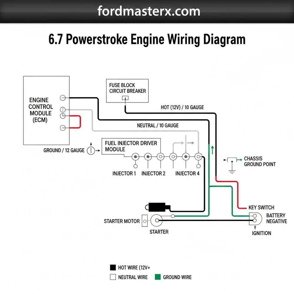
In the diagram above, you can observe the primary connection points. The common terminal grounds are clustered near the engine block and chassis, ensuring a low-resistance path back to the battery. In automotive applications, the ground wire serves a role similar to a neutral wire in residential settings, completing the circuit and allowing current to flow. However, because the vehicle chassis acts as a massive conductor, maintaining clean contact at every brass screw terminal and mounting bolt is essential for preventing electrical “noise” that can disrupt sensor data.
Step-by-Step Guide to Reading and Implementing Wiring Repairs

Interpreting a complex wiring schematic can be daunting for beginners. However, by breaking the process down into logical steps, you can isolate faults and perform professional-grade repairs. Use the following steps to navigate your wiring tasks effectively.
- Identify the Target Circuit: Start by identifying the specific component that is malfunctioning. Locate its symbol on the 6.7 powerstroke engine wiring diagram. This will show you the pin numbers on the PCM connector and the color of the wire traveling to the component.
- Verify the Wire Gauge and Color: Before making any cuts or splices, confirm the wire gauge. Using a wire that is too thin (higher gauge number) for a high-draw component like the fuel lift pump can cause the wire to overheat. Match the color and tracer exactly to the diagram to ensure you aren’t tapping into a different system.
- Locate the Common Terminal Ground: Many intermittent issues on the 6.7 Powerstroke stem from poor grounding. Use the diagram to find the shared ground points. Unlike a dedicated traveler wire in a home lighting circuit, automotive grounds often merge into a single “common terminal” or splice pack before reaching the frame.
- Test for Voltage and Continuity: With a digital multimeter, check for the presence of a “hot wire” signal. Set your meter to DC volts and check the power side of the connector. Then, switch to ohms to check the continuity of the ground wire. There should be very little resistance (less than 0.5 ohms) between the component ground and the battery negative terminal.
- Inspect Pin Tension and Terminals: Wiring issues aren’t always in the wire itself; often they are at the connection point. Inspect the brass screw connections or plastic pin connectors for signs of spreading or corrosion. A loose pin can cause a voltage drop that mimics a failed sensor.
- Trace Signal Paths: If the component has power and ground but still doesn’t function, trace the signal wire back to the PCM. This is where the diagram is most valuable, as it shows you which specific pin (e.g., Pin 42 on Connector C1284) should be receiving the data.
Never use a test light on the 6.7 Powerstroke sensor circuits. The high current draw of a traditional bulb-style test light can “back-feed” and fry the delicate internal circuitry of the PCM. Always use a high-impedance digital multimeter.
To perform these tasks, you will need a high-quality multimeter, a wire stripping tool, heat-shrink tubing, and a soldering iron for permanent repairs. Avoid using “vampire” style clip-on connectors, as they compromise the wire’s weather-tight seal and lead to internal corrosion over time.
Common Issues & Troubleshooting

The 6.7 Powerstroke engine is known for its durability, but its wiring harness is susceptible to specific environmental stresses. One of the most frequent problems is wire chafing. Because the engine generates significant vibration, the plastic looms can rub against the metal brackets of the engine, eventually wearing through the insulation. This often creates an intermittent short where a “hot wire” touches the engine block, causing the fuse to blow or the engine to enter “limp mode.”
Another common issue involves the Exhaust Gas Temperature (EGT) sensor connectors. These are located in high-heat areas under the truck. The heat can make the plastic connectors brittle and increase the resistance at the terminal. If your diagram shows a high resistance reading on these circuits, it is often the connector rather than the wire itself. By using the wiring diagram, you can identify which of the four EGT sensors is reporting an error based on the specific wire colors at the sensor plug.
- ✓ Check for 5V reference at the MAP sensor when “check engine” lights appear.
- ✓ Inspect the harness near the AC compressor for chafing against the frame.
- ✓ Verify that the main battery ground is not corroded at the frame rail.
Tips & Best Practices for Wiring Maintenance
When working with the 6.7 powerstroke engine wiring diagram, the goal is to restore the system to factory specifications. This means maintaining the integrity of the shielding and the weatherproofing of the harness. If you must replace a section of wire, ensure you are using automotive-grade TXL or GXL wire. These types of wire have thin-wall cross-linked polyethylene insulation that is resistant to oil, grease, and high engine temperatures.
When reconnecting multi-pin plugs, apply a small amount of dielectric grease to the rubber seal (not the metal pins themselves). This prevents moisture intrusion while ensuring the plastic housing doesn’t become stuck over time due to heat cycles.
Maintenance recommendations also include checking the voltage drop across the main power leads. Over time, the internal strands of the “hot wire” coming from the alternator can corrode, even if the insulation looks fine. By measuring the voltage at the alternator and then at the battery, you can determine if the cable is losing energy. A difference of more than 0.5 volts suggests that the cable gauge is no longer sufficient or the internal resistance has increased, necessitating a replacement.
Finally, always document your changes. If you have to bypass a failed section of the harness or move a ground wire to a new common terminal, mark it in your notes. Future troubleshooting will be significantly easier if you know exactly where the factory wiring has been modified. By following the 6.7 powerstroke engine wiring diagram and adhering to these best practices, you can ensure your diesel engine remains as reliable as the day it left the factory. Utilizing the right tools and understanding the relationship between voltage, ground, and signal wires will empower you to handle even the most complex electrical challenges with confidence.
Frequently Asked Questions
Where is the PCM located on a 6.7 Powerstroke?
The Powertrain Control Module (PCM) is located on the passenger side of the engine bay, mounted against the firewall. It is the central hub for the 6.7 Powerstroke engine wiring diagram, receiving signals from every major sensor to manage fuel timing and emissions.
What does the 6.7 Powerstroke wiring diagram show?
This diagram illustrates the complex network of power distribution, signal transmission, and grounding for the engine. It specifically details the wiring for the fuel injectors, turbocharger actuators, and various temperature sensors, helping technicians identify exactly where a circuit might be broken or shorted.
How many wires are in the 6.7 Powerstroke injector harness?
The injector harness typically features two wires per injector, but the main trunk contains dozens of wires leading to the common terminal block. Each injector requires a precise signal from the PCM to fire, making the integrity of these specific wires vital for engine performance.
What are the symptoms of a bad engine wiring harness?
A damaged harness often causes erratic engine behavior, such as random misfires, sudden stalling, or ‘limp mode.’ You may see various communication codes on a scan tool. Physical signs include frayed insulation on a hot wire or a loose ground wire causing intermittent power loss.
Can I repair the 6.7 Powerstroke wiring myself?
Minor repairs like fixing a broken connector or a damaged traveler wire are feasible for DIYers with good soldering skills. However, replacing the entire main engine harness is a labor-intensive task that requires significant disassembly of the top end of the engine and cooling system.
What tools do I need for electrical diagnosis?
To effectively use the wiring diagram, you need a high-quality digital multimeter, a test light, and a dedicated OBD-II scan tool. These tools allow you to check for continuity, verify 12V power at the hot wire, and ensure the neutral wire return paths are functional.


