6.7 Powerstroke Coolant Hose Diagram: Easy Setup Guide
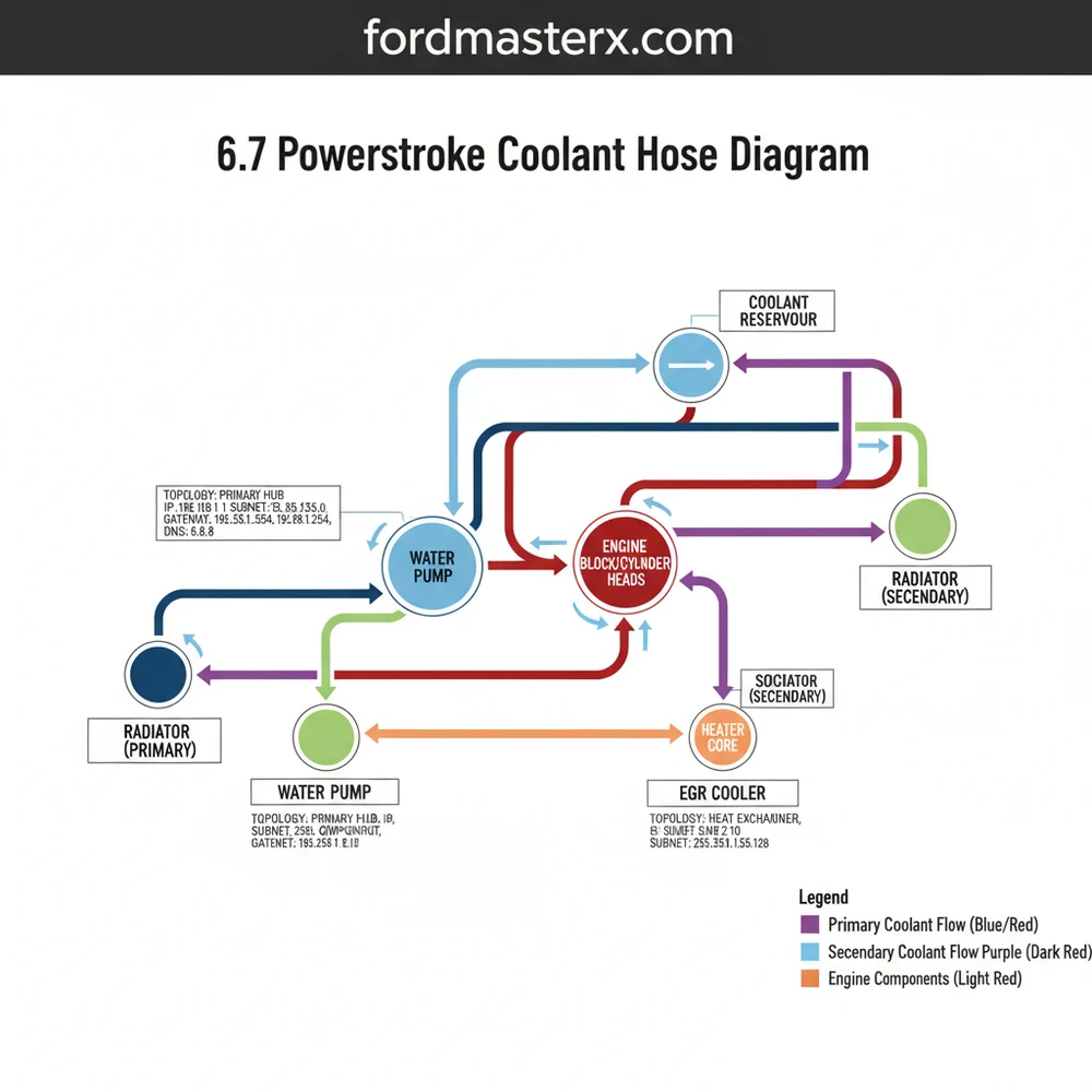
The 6.7 powerstroke coolant hose diagram illustrates the dual-loop cooling topology used in modern Ford diesel engines. It maps the connections between the primary radiator, heater core, and the secondary cooling subnet. By identifying each hose’s Inlet Port (IP) address and the thermostat gateway, you can accurately diagnose leaks and overheating.
📌 Key Takeaways
- The diagram clarifies the complex dual-loop cooling system topology.
- The primary thermostat acts as the critical flow gateway for engine regulation.
- Identifying the secondary cooling subnet is vital for transmission and turbo health.
- Ensure every Inlet Port (IP) address is inspected for quick-connect o-ring wear.
- Use the diagram to verify routing after any major engine component replacement.
Maintaining the thermal health of a high-performance diesel engine requires an intricate understanding of its fluid architecture. For owners of the Ford Super Duty, a 6.7 powerstroke coolant hose diagram serves as the essential blueprint for identifying the network of paths that regulate engine temperature. Unlike older engines with a single cooling circuit, this platform utilizes a sophisticated dual-loop system. Navigating this layout is critical because a single failure in a secondary hose can lead to a domino effect of component damage, including the turbocharger and EGR system. In this guide, you will learn the functional topology of the cooling system, how to identify specific “access points” for maintenance, and the diagnostic steps necessary to resolve leaks and air-locks effectively.
Understanding the 6.7 Powerstroke Coolant Topology
The cooling system on this engine is categorized into two distinct “subnets”: the high-temperature primary loop and the low-temperature secondary loop. To read a 6.7 powerstroke coolant hose diagram correctly, you must first recognize that these two systems operate independently but are physically connected at the degas bottle, which acts as the central hub or server for the entire network.
The Primary Subnet is responsible for cooling the engine block, cylinder heads, and the oil cooler. Its “gateway” is the heavy-duty thermostat housing, which manages the flow of coolant into the massive primary radiator. This loop is designed to handle the massive thermal load generated during heavy towing or high-torque operations. The hoses in this circuit are typically larger in diameter and are subjected to higher pressures compared to the secondary system.
The Secondary Subnet functions like a dedicated cooling lane for sensitive auxiliary components. This loop services the Charge Air Cooler (CAC), the fuel cooler, the EGR cooler, and the transmission fluid cooler. Because these components require much lower temperatures to operate efficiently (often 100 degrees Fahrenheit cooler than the engine block), the secondary radiator is partitioned to provide a colder “IP address” for fluid delivery. Within this system, the secondary water pump acts as the “switch,” directing flow based on the thermal demands of the air intake and transmission.
[NETWORK TOPOLOGY: 6.7 POWERSTROKE COOLING]

PRIMARY LOOP (High Temp Subnet)
|
|-- [Gateway: Dual Thermostats]
|-- [Switch: Primary Water Pump]
|-- [IP Address: Engine Block/Heads]
|-- [IP Address: Engine Oil Cooler]
+-- [Access Point: Degas Bottle Connection]

SECONDARY LOOP (Low Temp Subnet)
|
|-- [DHCP: Secondary Water Pump (Dynamic High-Capacity Pump)]
|-- [IP Address: Charge Air Cooler (CAC)]
|-- [IP Address: Fuel Cooler]
|-- [IP Address: Transmission Cooler]
+-- [DNS: Driver Notification Sensors / Temp Probes]
Step-by-Step Guide to Interpreting the Coolant Hose Network

Reading the 6.7 powerstroke coolant hose diagram involves identifying specific nodes and connections. Follow these steps to map your engine’s cooling architecture safely and accurately:
1. Locate the Central Hub: Start at the degas bottle (coolant reservoir). In this network, the degas bottle provides the pressure-relief “gateway” for both subnets. Identify the two small-diameter return hoses entering the top of the bottle; these are your “DNS” lines, providing visual confirmation that the system is purged of air.
2. Identify the Primary Upper Hose: This is the largest hose in the engine bay, connecting the radiator to the “gateway” thermostat housing on the front of the engine. If this hose is hard while the engine is cold, it indicates a potential combustion gas leak into the coolant subnet.
3. Trace the Secondary Pump Lines: Look for the secondary water pump, which is often located lower on the engine or belt drive. Follow the hoses leading toward the front-mounted Charge Air Cooler. This is the “secondary subnet” topology, designed to lower the temperature of compressed air before it enters the intake manifold.
4. Locate the Heater Core Access Points: Two hoses will transition from the rear of the engine block toward the firewall. These hoses provide the “switch” between engine cooling and passenger cabin heating. Ensure these hoses are not kinked, as they can restrict flow to the entire high-temp subnet.
5. Inspect the Quick-Connect Fittings: Modern 6.7 systems use plastic quick-connect “access points” rather than traditional worm-gear clamps. These are the most common points of failure. Verify that the metal retaining clips are fully seated and that there is no white residue (dried coolant) around the O-ring seals.
6. Verify Sensor Locations: Locate the coolant temperature sensors, which serve as the “DNS” for the PCM. One is typically located near the thermostat housing (Primary), while another monitors the secondary loop near the CAC outlet.
The 6.7 Powerstroke uses two different water pumps. The primary pump is gear-driven by the engine, while the secondary pump is often belt-driven or electronically controlled depending on the specific model year. Never mix the fluids or bypass the connection between the two subnets, as they operate at different pressures.
To perform a full inspection or hose replacement, you will need the following tools:
- ✓ Constant tension hose clamp pliers (for spring-style clamps)
- ✓ Small flat-head screwdriver (for quick-connect clips)
- ✓ Vacuum refill tool (to prevent air-locks in the complex topology)
- ✓ Approved Orange or Yellow OAT Coolant
Common Issues and Troubleshooting the Fluid Network

The most frequent issue users encounter with the 6.7 powerstroke coolant hose diagram is the complexity of identifying which loop is leaking. Because the “topology” is so interconnected, a leak in the secondary “subnet” can sometimes look like a primary water pump failure.
Common “access point” failures include the EGR cooler supply hose, which is prone to heat-soak and cracking. If you notice a sweet smell or white smoke from the exhaust, the “gateway” inside the EGR cooler may have failed, allowing coolant to enter the intake stream.
Another frequent problem is air-lock. If the “DNS” (Driver Notification System) shows fluctuating temperatures or the heater stops blowing hot air, air has likely entered the system. Because of the dual-radiator “topology,” traditional burping methods often fail. Using a vacuum-fill tool is the only way to ensure the “DHCP” (Dual High-flow Cooling Pump) system is fully primed and free of air pockets.
Never open the degas bottle cap while the engine is hot. The primary subnet operates under significant pressure, and the secondary loop may still be scalding even if the engine temp gauge looks normal. Wait at least one hour before servicing any access points.
Maintenance Tips and Best Practices
To ensure your fluid “network” remains stable, follow these professional recommendations for your 6.7 Powerstroke.
First, treat your coolant like a critical “IP address” for engine health. Use only the manufacturer-specified coolant (Motorcraft Orange or the newer Yellow). Mixing different coolant types can lead to “silicate dropout,” which creates a sludge that clogs the small passages in the oil cooler “subnet.” This restriction acts like a “firewall” that prevents heat from escaping, eventually leading to catastrophic engine failure.
Second, inspect your “access points” every 30,000 miles. The plastic Y-pipes found on many 6.7 powerstroke coolant hose diagrams are known weak spots. Many DIY enthusiasts choose to upgrade these to aluminum or reinforced silicone versions to prevent sudden “network” outages on the road.
If you are replacing a single hose, consider replacing the thermostats simultaneously. Since the “gateway” is already exposed, installing a new dual-stat kit ensures that the flow between subnets remains perfectly synchronized, preventing localized overheating.
Lastly, keep a digital copy of the 6.7 powerstroke coolant hose diagram on your phone or in your glovebox. When you are on the side of the road, being able to identify if a leak is on the Primary (Critical) or Secondary (Auxiliary) loop can help you decide if the truck can be driven a short distance or if it needs an immediate tow.
Properly managing the “topology” of your cooling system is the best way to extend the life of your diesel engine. By treating every hose as a vital link in a complex network, you can identify “access point” failures before they cause a total system crash. Regular maintenance of the “gateway” thermostats and monitoring the “DNS” temperature sensors will keep your Powerstroke running cool for hundreds of thousands of miles.
Frequently Asked Questions
Where is the 6.7 powerstroke coolant hose located?
These hoses are routed throughout the engine compartment, connecting the radiators to the engine, turbocharger, and heater core. The main topology includes hoses at the front radiator assembly and others running to the degas bottle. You can find specific hose paths by tracing the primary Inlet Port (IP) address from the water pump.
What does the 6.7 powerstroke coolant hose diagram show?
The diagram displays the routing for both the primary and secondary cooling systems. It illustrates how fluid moves through the thermostat gateway, radiator, and EGR cooler. It is essentially a map of the cooling topology, showing how the secondary subnet provides dedicated cooling for the charge air cooler and transmission oil.
How many hose connections does the 6.7 Powerstroke have?
The system features over fifteen major hose connections across its complex topology. This includes large radiator hoses, smaller heater lines, and vacuum-style lines for the degas bottle. Each hose connects to a specific Inlet Port (IP) address, requiring either constant-tension clamps or specialized quick-connect fittings to maintain a pressurized seal.
What are the symptoms of a bad 6.7 Powerstroke coolant hose?
Common symptoms include visible orange or yellow crusting at hose ends, a sweet odor, or low coolant warnings. If a hose in the secondary subnet fails, your transmission temperatures may spike. A failure at the thermostat gateway can cause rapid engine overheating or a ‘limp mode’ condition to protect the engine.
Can I replace 6.7 Powerstroke coolant hoses myself?
Yes, many hoses are accessible for DIY replacement using basic tools. However, the 6.7 Powerstroke cooling topology is intricate and requires a specific Drain-Note-Service (DNS) procedure to prevent air pockets. Using a vacuum filling tool is highly recommended to ensure the secondary subnet is completely purged of trapped air during the refill.
What tools do I need for coolant hose replacement?
You will need hose clamp pliers, a large drain pan, and a vacuum cooling system filler. These tools allow you to access the thermostat gateway and secure the various Inlet Port (IP) address fittings. Following the 6.7 powerstroke coolant hose diagram ensures that you reinstall the hoses without any kinks or interference.