6.0 Powerstroke Intake Manifold Diagram: Diagnosis Guide
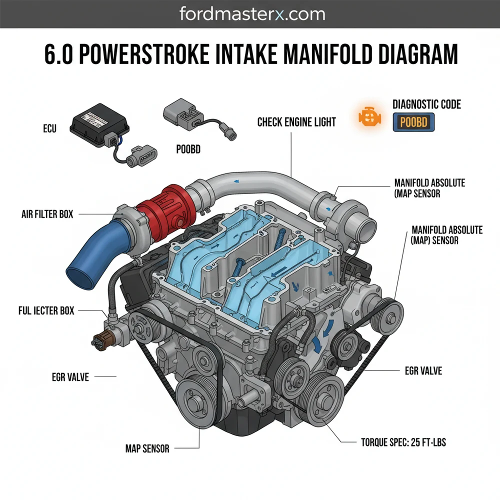
A 6.0 Powerstroke intake manifold diagram shows the dual-plane aluminum housing that routes pressurized air from the turbocharger to the cylinder heads. It includes ports for the EGR valve, MAP sensor, and temperature sensors. Understanding this layout is essential for locating vacuum leaks or replacing gaskets to maintain proper torque spec levels.
📌 Key Takeaways
- Visualizing the airflow path from the turbo to the intake valves
- Identifying the location of the EGR valve and MAP sensor ports
- Replacing all gaskets and O-rings whenever the manifold is removed
- Cleaning carbon buildup from internal ports to restore airflow
- Using the diagram to locate boost leaks or failed sensor connections
The 6.0L Powerstroke diesel engine, used in Ford Super Duty trucks from 2003 to 2007, is renowned for its power and notorious for its complexity. At the center of this engine’s respiratory system lies the intake manifold. Unlike simple gasoline engines, the 6.0 Powerstroke intake manifold is a heavy, cast-aluminum component designed to distribute high-pressure charged air from the turbocharger into the cylinder heads while also integrating the Exhaust Gas Recirculation (EGR) system and the oil cooler. For the DIY enthusiast, understanding the 6.0 Powerstroke intake manifold diagram is more than just an academic exercise; it is a necessity for performing common repairs like EGR cooler deletes, oil cooler replacements, or fixing stubborn boost leaks. This guide provides a comprehensive breakdown of the manifold’s architecture, sensor locations, and the technical specifications required to service it correctly.
Main Components and Features of the 6.0 Intake Manifold
The 6.0 Powerstroke intake manifold is a “split-level” design that sits directly in the “V” of the engine block. To navigate a diagram effectively, you must first identify the primary structural elements and the peripheral components attached to it. The manifold is primarily responsible for channeling cooled, compressed air from the Intercooler (Charge Air Cooler) into the eight intake ports.
- The Plenum and Runners: The manifold features two large main runners, often referred to as “donkey ears” due to their shape. These distribute air to the four intake ports on each cylinder head. The internal volume is specifically tuned to maintain boost pressure and airflow velocity.
- EGR Valve Port: Located at the front-center of the manifold, this is where the EGR valve sits. It regulates the flow of exhaust gases back into the intake stream to lower combustion temperatures.
- MAP Sensor Nipple: On the passenger side rear of the manifold, there is a small brass or plastic nipple. A rubber hose connects this nipple to the Manifold Absolute Pressure (MAP) sensor mounted on the firewall. This is a critical point for monitoring boost levels.
- IAT2 Sensor Port: Not to be confused with the IAT1 sensor (located near the air filter), the Intake Air Temperature 2 (IAT2) sensor is threaded directly into the manifold, usually toward the rear on the driver’s side. It measures the temperature of the air after it has been compressed by the turbo and cooled by the intercooler.
- Oil Cooler Connection: The intake manifold does not just carry air; it also acts as a structural cap for the oil cooler. The manifold must be removed to access the oil cooler located in the engine valley.
How to Read and Use the Intake Manifold Diagram

When looking at a technical diagram of the 6.0 Powerstroke intake manifold, you are usually looking at a “top-down” exploded view. This perspective is vital for understanding the bolt pattern and the sequence of removal. The manifold is held down by 10 primary bolts (M6 x 1.0 thread) of varying lengths. A standard diagram will label these bolts to ensure they are returned to their specific holes.
Bolt Locations and Measurements:
Most of the bolts used on the manifold are 95mm or 100mm in length. It is crucial to track these during disassembly. In a diagram, you will see the bolts numbered 1 through 10. These numbers usually correspond to the torque sequence, not just the location. The sequence starts from the center and works outward in a crisscross pattern to ensure the manifold seats evenly against the cylinder head gaskets and the oil cooler’s “J-tube” or discharge port.
Wiring and Harness Routing:
A comprehensive diagram will also show the fuel injection harness and the engine sensor harness as they lay across the manifold. The 6.0 harness is notorious for “chafing.” Key wire colors to look for on the manifold sensors include:
- MAP Sensor: Light Green/Red (Signal), Gray/Red (Reference), and Violet/White (Ground).
- IAT2 Sensor: Gray/Red (Reference) and Green/Black (Signal).
Practical Tips for Intake Manifold Maintenance

Removing and reinstalling the intake manifold is a labor-intensive process that usually takes a DIYer 4 to 8 hours. To make the process smoother, follow these practical tips gathered from veteran diesel mechanics:
- Organize Your Bolts: Use a piece of cardboard and poke holes in it to mirror the intake manifold diagram. As you remove each bolt, place it in the corresponding hole in the cardboard. This prevents using a long bolt in a shallow hole, which can crack the manifold casting or the engine block.
- Clean the “V”: Before lifting the manifold, use compressed air to blow out the engine valley. Debris, acorns, and dirt often collect under the manifold and can fall into the open intake ports of the cylinder heads once the manifold is removed.
- Gasket Preparation: The 6.0 uses reusable silicone-beaded gaskets. However, if they are flattened or brittle, replace them. Ensure the mating surfaces on the cylinder heads are cleaned with a plastic scraper and brake cleaner. Do not use a metal scraper, as it can gouge the aluminum.
- Inspect the “Blue Hose”: The manifold connects to the EGR cooler via a small silicone hose (often blue or orange). This is a common failure point. Always replace this hose and the associated O-rings while the manifold is off.
Troubleshooting Common Manifold Issues
If you are consulting a diagram because your truck isn’t running correctly, you are likely dealing with one of three common 6.0 Powerstroke intake issues: carbon clogging, boost leaks, or sensor failure.
1. Carbon Buildup: Because the EGR system introduces exhaust soot into the intake, the manifold can become heavily restricted over time. If your diagram shows the EGR valve port, this is usually where the “sludge” is thickest. If you notice a loss of power and black smoke, you may need to remove the manifold and have it “hot-tanked” or cleaned with a heavy-duty degreaser.
2. Boost Leaks: A leak at the intake manifold will result in a “hissing” sound under load and a significant drop in power. Use your diagram to locate the mating surfaces and the MAP sensor hose. A common failure point is the MAP sensor hose cracking or the nipple becoming clogged with soot, which gives the computer a false reading of zero boost.
3. Torque and Sealing Issues: If the manifold was recently removed and the truck now runs poorly, check the torque. The specification for the 6.0 intake manifold bolts is 96 inch-pounds (not foot-pounds!). Over-tightening will warp the manifold or snap the small M6 bolts, while under-tightening will lead to boost leaks and oil seepage from the oil cooler area.
Troubleshooting Table: Sensor Readings
| Sensor | Normal Reading (Idle) | Common Failure Symptom |
|---|---|---|
| MAP Sensor | ~14.7 PSI (Sea Level) | Low power, no turbo vane movement |
| IAT2 Sensor | Ambient + 20-40°F | Poor fuel economy, rough cold start |
| EGR Valve | 0% DC (at idle) | Stalling, surging, excessive smoke |
Conclusion
The 6.0 Powerstroke intake manifold is more than just a piece of metal; it is a crossroads where air, oil, and exhaust meet. By using a detailed diagram to understand the bolt patterns, sensor locations, and torque specifications, DIY enthusiasts can tackle complex repairs with confidence. Remember to prioritize cleanliness, stick strictly to the 96 inch-pound torque limit, and always inspect the EGR and oil cooler connections while the manifold is accessible. With the right approach, you can ensure your 6.0L engine breathes clearly and performs at its peak for years to come.
Step-by-Step Guide to Understanding the 6.0 Powerstroke Intake Manifold Diagram: Diagnosis Guide
Identify the intake manifold and its associated sensors like the MAP and IAT2.
Locate the mounting bolts and electrical connectors linked to the engine harness.
Understand how the EGR valve integrates with the manifold to recirculate exhaust gases.
Apply the correct torque spec when reinstalling the 14 bolts in the proper sequence.
Verify that all gaskets are seated correctly to prevent any boost pressure loss.
Complete the installation by checking for a check engine light using a scanner.
Frequently Asked Questions
Where is the intake manifold located?
The intake manifold on a 6.0 Powerstroke sits directly in the engine valley, nestled between the two cylinder heads. It is positioned beneath the turbocharger and oil cooler, requiring the removal of several top-end components, including the fuel filter housing and air intake, to access it fully for repairs.
What does the intake manifold diagram show?
The diagram displays the routing of intake air, the location of mounting bolts, and the integration of the EGR system. It also highlights ports for the MAP sensor and IAT2 sensor, which send data to the ECU. This visual aid is crucial for identifying potential leak points and connections.
How many bolts secure the intake manifold?
The 6.0 Powerstroke intake manifold is typically secured by 14 bolts. These fasteners must be tightened to a specific torque spec to prevent leaks. Following the correct tightening sequence shown in the diagram ensures the gaskets compress evenly against the cylinder heads for a perfect, long-lasting seal.
What are the symptoms of a bad intake manifold?
A failing manifold or leaking gasket often triggers a check engine light and a specific diagnostic code like P0401. You may notice reduced boost pressure, poor fuel economy, or excessive black smoke. Using an OBD-II scanner can help confirm if sensor readings are within normal ranges during operation.
Can I replace this myself?
Replacing the intake manifold is a complex DIY task that requires advanced mechanical skills. It involves disconnecting fuel lines, removing the turbo, and carefully managing the cooling system. While possible with the right tools and a detailed diagram, it is time-consuming and requires strict attention to fastener torque.
What tools do I need for this task?
You will need a comprehensive socket set, including 10mm and 13mm deep sockets, and a reliable torque wrench. Additionally, a shop vacuum is recommended to clean the engine valley, along with an OBD-II scanner to clear any diagnostic codes stored in the ECU after the repair is finished.


