6.0 Powerstroke Ford 6.0 Diesel Vacuum Line Diagram Guide
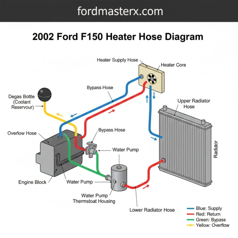
The 6.0 Powerstroke Ford 6.0 diesel vacuum line diagram maps the path from the passenger-side electric pump to the reservoir and interior HVAC plenum. It ensures vacuum reaches the blend doors, allowing the blower motor to direct air across the evaporator and heater core for proper climate control and defrost functions.
📌 Key Takeaways
- Traces vacuum flow from the electric pump to the HVAC blend doors.
- Crucial for fixing the ‘default to defrost’ air direction issue.
- Vacuum leaks can cause the electric pump to run continuously, leading to failure.
- Ensure all rubber boots are tight to maintain refrigerant cooling efficiency.
- Use this diagram when troubleshooting 4×4 engagement or HVAC vent switching.
Navigating the complexities of the Ford Super Duty cooling and ventilation system requires a clear understanding of the 6.0 powerstroke ford 6.0 diesel vacuum line diagram. Unlike gasoline engines that utilize manifold vacuum, the 6.0L Powerstroke diesel engine relies on a dedicated electric vacuum pump to operate essential components like the HVAC (Heating, Ventilation, and Air Conditioning) doors and the Pulse Vacuum Hubs (PVH) for four-wheel-drive engagement. This guide is designed to help you identify every line, connector, and solenoid within that system. Whether you are dealing with vents that are “stuck on defrost” or a four-wheel-drive system that refuses to engage, having a comprehensive map of the vacuum routing is the first step toward a successful repair. By the end of this article, you will understand how vacuum pressure integrates with the broader HVAC system to provide cabin comfort and mechanical reliability.
Detailed Component Analysis and Diagram Breakdown
The vacuum system on a 6.0L Powerstroke is a closed-loop pneumatic network. At its heart is the electric vacuum pump, typically mounted on the passenger-side inner fender well. This pump maintains a constant vacuum level in a plastic reservoir tank. While the refrigerant is managed by the compressor and cooled by the condenser located in front of the radiator, the vacuum system is what actually directs the resulting air. Without vacuum, the air handler (the plenum assembly inside the dash) cannot move its internal doors to direct air through the evaporator or the heat exchanger (heater core).
On the 6.0L Powerstroke, the vacuum system is “fail-safe” to defrost. If you lose vacuum pressure due to a cracked line or a dead pump, the internal springs in the dash actuators will default the airflow to the windshield for safety reasons.
The diagram consists of several primary branches. The main line runs from the pump to the vacuum reservoir. From the reservoir, a “T” fitting splits the vacuum in two directions. One branch leads toward the firewall, entering the cabin to feed the HVAC control head. The other branch runs toward the Pulse Vacuum Hub (PVH) solenoid, which is responsible for locking the front hubs when 4WD is selected on the dash. In the HVAC circuit, the vacuum allows the driver to toggle between the return duct settings, floor vents, and dash vents. If the blower motor is running but air is only coming out of the top of the dash, you are likely looking at a breach in the lines shown in our diagram.
    [Electric Pump] ----> [Vacuum Reservoir]
                               |
            _|_
           |                                       |
    [PVH Solenoid]                         [Firewall Port]
           |                                       |
    _|_                       |
    |             |                       |               |
[Left Hub]   [Right Hub]           [HVAC Control Unit] [Recirc Door]
                                          |
                              |
                              |           |           |
                        [Defrost]      [Floor]      [Vent]
Note: Lines are typically black nylon; some specialized versions use color-coded stripes (Red/Blue/White) for specific door actuators.
Step-by-Step Guide to Reading and Implementing the Diagram

Interpreting a vacuum diagram for the first time can be intimidating, especially with the cramped engine bay of a 6.0L diesel. Follow these steps to trace your system and identify potential leaks or installation errors. Before beginning, ensure you have a handheld vacuum pump with a gauge, as this is the most effective tool for testing individual sections of the line.
-
1. Locate the Primary Source:
Find the electric vacuum pump on the passenger side fender. Turn the ignition to the “ON” position (engine off). You should hear the pump hum for several seconds as it builds pressure. If it never stops running, there is a leak further down the line. -
2. Inspect the Reservoir Tank:
Trace the thickest black line from the pump to the plastic reservoir hidden beneath the cowl or battery tray. These tanks can develop hairline cracks. Use your handheld gauge to see if the tank holds 15-20 inches of mercury (inHg). -
3. Trace the PVH Solenoid Branch:
Follow the line from the reservoir to the solenoid mounted on the passenger fender. From here, two lines drop down toward the frame rails. These often rot where they transition from nylon to rubber near the wheel wells. -
4. Identify the HVAC Firewall Entry:
Locate the smaller diameter line that passes through the firewall near the evaporator housing. This line supplies vacuum to the interior air handler. Ensure the rubber grommet at the firewall is intact and hasn’t pinched the line. -
5. Check the Vacuum Actuators:
Under the dashboard, the vacuum lines connect to various actuators that move the blend doors. Using the diagram, verify that the white, red, and blue lines are connected to their respective ports. This determines if air is pushed through the heat exchanger for warmth or across the evaporator for cooling. -
6. Verify Recirculation Logic:
The return duct is managed by the recirculation door. If your AC feels weak, check the vacuum line leading to the recirc door actuator (usually located behind the glovebox). Without vacuum, it won’t pull cabin air back through the system, forcing the refrigerant to work harder to cool hot outside air.
Never apply more than 25 inHg of vacuum to the system components with a manual pump. Excessive pressure can rupture the delicate diaphragms inside the HVAC actuators, requiring a complete dashboard removal to replace.
Common Issues and Troubleshooting
The most frequent failure on the 6.0L Powerstroke is the “defrost only” condition. When the vacuum pump fails or a line is severed, the system defaults to the windshield. This is often caused by the vacuum lines near the front hubs. Because these lines are exposed to road salt, heat, and suspension movement, they are prone to cracking. A leak at the hub can actually prevent the blower motor from being able to push air through the dash vents because the leak “robs” the reservoir of its pressure.
Another common culprit is the 4WD PVH solenoid. If the internal seals of the solenoid fail, it creates a constant vacuum leak. You can diagnose this by disconnecting the line to the solenoid and plugging it; if your AC vents suddenly start working correctly, you have found the source of the leak. Furthermore, check the condition of the compressor clutch engagement. If the vacuum pump is running constantly, it can occasionally create electrical interference or signify a larger pneumatic failure that affects the overall climate control logic.
If your vacuum pump runs for more than 15 seconds after you turn the key to “ON,” you have a leak. Use a pair of needle-nose pliers to gently pinch off sections of the vacuum line to isolate which “branch” of the diagram contains the leak.
Maintenance Tips and Best Practices
To ensure your HVAC system remains functional, regular inspection of the vacuum lines is necessary. The factory nylon lines become brittle over time due to the extreme heat generated by the 6.0L engine’s turbocharger and condenser. Replacing these with high-quality silicone vacuum tubing is a popular upgrade. Silicone is much more resistant to heat-cycling and won’t crack as easily as the original equipment manufacturer (OEM) plastic.
When performing maintenance, pay close attention to the area around the evaporator housing. Debris can sometimes clog the return duct, causing the blower motor to work harder and creating a pressure differential that stresses the vacuum-operated doors. Keeping the cabin air filters (if equipped) clean and ensuring the exterior cowl is free of leaves will prolong the life of your internal actuators. Additionally, always use high-quality replacement parts for the PVH solenoid; cheaper aftermarket versions are known to leak straight out of the box, leading to frustration and wasted diagnostic time.
Finally, remember that the vacuum system is just one part of the climate control puzzle. While the 6.0 powerstroke ford 6.0 diesel vacuum line diagram will solve vent-direction issues, temperature issues are usually related to the refrigerant level or the heat exchanger. By maintaining a leak-free vacuum circuit, you ensure that the mechanical side of your HVAC system is ready to deliver the conditioned air exactly where you need it most.
Frequently Asked Questions
Where is the vacuum pump located?
The electric vacuum pump on the 6.0 Powerstroke is located on the passenger-side inner fender well, just behind the battery. This pump is responsible for providing the necessary vacuum to operate the HVAC doors and the pulse-vacuum cooling hubs, ensuring the system functions independently of engine load.
What does the 6.0 diesel vacuum diagram show?
This diagram illustrates the routing from the vacuum pump to the reservoir tank and through the firewall. It highlights how vacuum acts upon the blower motor housing doors to route air past the evaporator, ensuring that cooled refrigerant can effectively lower the cabin temperature during AC operation.
How many vacuum connections does the HVAC system have?
The system typically features one primary supply line from the reservoir that splits into several smaller lines behind the dash. These connections control various actuators for the floor, vent, and defrost modes. Proper vacuum pressure is required for the compressor to cycle correctly and maintain cabin comfort.
What are the symptoms of a bad vacuum line?
The most common symptom is air only blowing from the defrost vents regardless of the selected setting. Other signs include a vacuum pump that never shuts off or poor AC performance because the condenser and evaporator cannot receive proper airflow to facilitate the heat exchange of the refrigerant.
Can I replace the vacuum lines myself?
Yes, replacing these vacuum lines is a common DIY task. Most lines use simple rubber elbows and plastic tubing that can be swapped without specialty tools. Following the diagram is essential to ensure that the blower motor and actuators are connected to the reservoir in the correct sequence.
What tools do I need for vacuum line repair?
You will need a handheld vacuum pump with a gauge to test for leaks and identify which section of the line is compromised. A basic set of pliers can help remove brittle rubber boots from the pump or condenser area, and silicone spray helps slide new lines onto fittings.