6.0 Powerstroke FICM Wiring Diagram: Easy Setup Guide
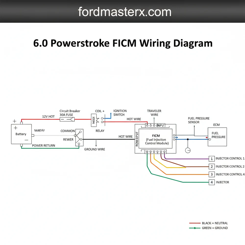
The 6.0 Powerstroke FICM wiring diagram details the connections between the Powerstroke Control Module, the injectors, and the FICM. It identifies high-voltage output pins, ground paths, and signal inputs. By tracing the hot wire for power and ensuring a solid ground, you can diagnose low voltage issues that cause rough starts.
📌 Key Takeaways
- The diagram maps the 48V power supply to fuel injectors
- Identify the X1, X2, and X3 connectors for accurate pin testing
- Safety first: disconnect batteries to avoid high-voltage shocks
- Check for harness chafing specifically near the valve covers
- Use the diagram to verify consistent voltage during cold crank cycles
If you own a Ford Super Duty or Excursion equipped with the 6.0-liter engine, understanding the 6.0 powerstroke ficm wiring diagram is essential for maintaining engine performance. The Fuel Injection Control Module (FICM) is the nerve center of your fuel system, responsible for converting low battery voltage into the high-voltage pulses required to fire the hydraulic electronic unit injectors (HEUI). When your truck experiences a hard start, rough idle, or a total no-start condition, the wiring harness and its connections are often the primary suspects. This guide provides a comprehensive breakdown of the wiring architecture, helping you identify pin locations, wire colors, and essential voltage specifications to keep your engine running smoothly.
The FICM is located on the driver-side valve cover, protected by a heat shield, and is connected to the engine via three primary multi-pin connectors. To interpret a 6.0 powerstroke ficm wiring diagram correctly, you must first distinguish between the three main plugs: X-1, X-2, and X-3. The X-1 and X-2 connectors are responsible for sending high-voltage signals to the fuel injectors, while the X-3 connector handles the logic power, ground wire connections, and communication with the Power Control Module (PCM). Each connector is color-coded or keyed differently to prevent incorrect installation, usually appearing in shades of black, green, or gray.
Within these connectors, the wiring follows a specific sequence. The X-3 connector (closest to the firewall) includes the crucial “logic” wires. This is where you will find the 12-volt “hot wire” that triggers the FICM to wake up when the ignition is turned to the “On” position. Unlike household electrical systems that might utilize a traveler wire or a neutral wire for switching, the Powerstroke uses a high-speed CAN-bus data link to coordinate injection timing. The X-1 and X-2 connectors utilize heavy-gauge wiring to carry the 48-volt (or sometimes 58-volt in performance applications) pulses to the injectors. Each wire in these harnesses is color-striped to correspond with a specific cylinder, ensuring the firing order remains synchronized with the crankshaft position.
The FICM internal power board converts 12V DC from the batteries to 48V DC. If your voltage drops below 45V during cranking or operation, the FICM is failing and may damage your injectors.
Reading and interpreting the 6.0 powerstroke ficm wiring diagram requires a methodical approach. Follow these steps to map out your harness and ensure every connection is secure:
- Identify the Connector Orientation: Begin by facing the FICM from the driver-side fender. The connector nearest to the front of the truck is X-1 (Cylinders 1, 4, 6, 7), the middle is X-2 (Cylinders 2, 3, 5, 8), and the rear is X-3 (Power/Communication).
- Locate the Ground Wire Points: Automotive DC systems rely heavily on a clean circuit return. Trace the black wires from the X-3 connector to the engine block or chassis ground. Ensure these connections are free of corrosion, as a weak ground can cause phantom voltage drops.
- Inspect the Power Feed: Locate the heavy-gauge red or orange wires. These are the main “hot wire” feeds coming from the FICM relay. Ensure the 50-amp fuse in the under-hood power distribution box is intact before testing for voltage at the plug.
- Check Communication Pins: On the X-3 connector, identify the CAN-high and CAN-low pins. These allow the PCM to tell the FICM exactly when to fire. If these wires are frayed or shorted, the truck will not start even if the FICM has power.
- Verify Injector Harness Integrity: Move to the X-1 and X-2 plugs. Look for the twisted-pair wiring. The 6.0 uses twisted pairs to reduce electromagnetic interference (EMI). Any breaks in the insulation here can cause a “short to ground” code.
- Test Pin-to-Pin Continuity: Using a digital multimeter, check for continuity between the FICM plug pins and the corresponding injector terminals. A reading of more than 0.5 ohms indicates excessive resistance in the wire.
To perform these tasks, you will need a few essential tools. A high-quality digital multimeter is non-negotiable for checking voltage and resistance. You should also have a set of back-probe pins to test circuits while they are connected, as piercing the wire insulation can lead to future corrosion. While residential electricians might use a brass screw to secure a common terminal, automotive wiring uses plastic locking tabs and weather-pack seals. Having a small flat-head screwdriver or a specialized terminal release tool will prevent you from breaking these brittle plastic clips.
Always disconnect the batteries before unplugging the FICM. The capacitors inside the module hold a significant charge and can cause an electrical arc if the connectors are pulled while the system is energized.
One of the most frequent problems users encounter is the dreaded “chafing” issue. Because the 6.0 Powerstroke engine produces significant vibration, the wiring harness often rubs against the intake manifold or the FICM mounting bracket. This friction wears through the insulation, causing a hot wire to touch a ground wire or the engine block. This results in intermittent stalling or “contribution” codes for specific cylinders.
By referencing the 6.0 powerstroke ficm wiring diagram, you can pinpoint which wire corresponds to the fault code you are seeing. For example, if you have a code for Cylinder 3, you know to focus your inspection on the X-2 connector and the specific color-coded wire pair associated with that cylinder. Look for warning signs like “hiccups” while driving over bumps, which usually indicates a loose connection or a wire that is briefly shorting out. If you find that the plastic connectors have become brittle and the locking tabs have snapped off, it is best to seek professional help or replace the harness entirely, as a loose plug can lead to arched terminals and permanent module damage.
When reinstalling the harness, use plastic “looming” or high-temperature tape on areas where the wires come close to the engine block. Adding a small amount of dielectric grease to the connector seals can also prevent moisture intrusion and future corrosion.
For those looking to save costs, diagnosing the wiring yourself before replacing the entire FICM is a smart move. Many truck owners spend hundreds of dollars on a new module only to find the problem was a $10 relay or a loose common terminal connection. When inspecting the system, pay close attention to the wire gauge. The power and ground wires are significantly thicker than the signal wires because they must carry high current without overheating. If you notice any wire that looks swollen or has a “burnt” smell, it has likely been compromised by internal resistance and must be replaced.
- ✓ Maintain Battery Health: Low battery voltage is the number one killer of FICMs. Ensure your batteries and alternator are in top shape.
- ✓ Heat Management: Ensure the factory heat shield is always installed. The heat from the turbocharger can cook the internal components of the FICM.
- ✓ Use OEM Connectors: If you must repair a plug, use high-quality pigtails. Cheap aftermarket connectors often have poor pin tension, leading to intermittent signals.
- ✓ Monitor Voltage: Use an OBD-II monitor to keep an eye on “FICM Main Voltage” while driving. It should stay between 47V and 48.5V.
In summary, the 6.0 powerstroke ficm wiring diagram is a vital tool for any DIY mechanic or truck enthusiast. By understanding the relationship between the logic power, the ground wire network, and the high-voltage injector pulses, you can demystify one of the most complex parts of the Ford diesel engine. Whether you are dealing with a dead battery, a frayed harness, or a failing power board, having a clear map of the wiring ensures that your repairs are accurate and effective. Always prioritize safety, use the correct tools, and take the time to inspect the small details that make a big difference in the longevity of your Powerstroke engine.
Step-by-Step Guide to Understanding the 6.0 Powerstroke Ficm Wiring Diagram: Easy Setup Guide
Identify the three main harness connectors (X1, X2, and X3) on the module.
Locate the common terminal points where the main power supply enters the FICM board.
Understand how the traveler wire signals communicate timing data from the PCM to the module.
Connect your multimeter to the power pins to verify a consistent 48-volt output.
Verify that the main ground wire is securely fastened to the engine block for continuity.
Complete the inspection by checking the injector harness for any signs of heat-related chafing.
Frequently Asked Questions
Where is the 6.0 Powerstroke FICM located?
The Fuel Injection Control Module (FICM) is located on the driver’s side valve cover of the 6.0L Powerstroke engine. It is mounted on four rubber vibration isolators. To access it, you usually need to remove the air intake assembly and potentially move the coolant degas bottle for better connector clearance.
What does a FICM wiring diagram show?
This diagram provides a map of the electrical communication between the FICM, the engine injectors, and the PCM. It details how high voltage reaches the solenoids and identifies the neutral wire equivalent return paths. It helps you trace circuits that cause misfires, injector circuit codes, or total engine stalls.
How many connections does the 6.0 FICM have?
The FICM utilizes three primary connectors, often referred to as X1, X2, and X3. These include a 24-pin and a 32-pin connector for the injector harness and a smaller power connector. Together, they manage the high-voltage pulses and common terminal signals required to actuate the fuel injectors precisely.
What are the symptoms of a bad 6.0 FICM?
Common symptoms of a failing FICM include hard starting when the engine is cold, white smoke from the exhaust, and rough idling. You may also notice a loss of power or see fault codes like P0611. If the internal power board fails to maintain 48 volts, the engine won’t run.
Can I install or replace the FICM myself?
Most owners can replace or test a FICM themselves with basic hand tools. Testing requires a multimeter to check voltage at the pins. Replacing the unit involves unplugging the three main harnesses and unbolting the module from its bracket. Always ensure the batteries are disconnected before starting any electrical work.
What tools do I need for FICM troubleshooting?
You will need a digital multimeter to verify the 48-volt output. A 10mm socket and ratchet are required to remove the mounting bolts. A small flathead screwdriver or pick tool helps in releasing the locking tabs on the wiring harness connectors, which can become brittle and difficult to release.


