6.0 Powerstroke Engine Bay Diagram: Identification Guide
A 6.0 Powerstroke engine bay diagram identifies the layout of the turbocharger, fuel filters, FICM, and cooling system. It maps out key sensors and mechanical parts, allowing owners to locate the ECU and other modules quickly. This visual guide is essential for diagnosing leaks, electrical issues, or performing routine fluid changes.
📌 Key Takeaways
- Simplifies the complex identification of high-pressure diesel components
- The FICM and turbocharger are the most critical parts to locate
- Always depressurize the fuel and oil systems before service for safety
- Use the diagram to trace wiring harnesses for potential shorts or chafing
- Refer to this map when diagnosing no-start conditions or power loss
For any Ford Super Duty owner or diesel technician, navigating the complex layout of a Navistar-designed 6.0L engine can be a daunting task. Understanding a 6.0 powerstroke engine bay diagram is the first step in performing routine maintenance, diagnosing performance issues, or executing a full bulletproofing project. This guide provides a detailed visual and technical breakdown of the engine compartment, identifying critical sensors, fluid reservoirs, and mechanical assemblies. By the end of this article, you will be able to locate components like the FICM, interpret diagnostic signals, and manage the intricate cooling system with professional confidence.
Comprehensive Breakdown of the 6.0 Powerstroke Engine Bay
The 6.0 Powerstroke engine bay is notoriously crowded, often described by mechanics as “ten pounds of hardware in a five-pound bag.” To read the diagram effectively, you must understand the primary zones: the top-side cooling and intake area, the high-pressure oil system at the rear, and the electrical control center. Central to the layout is the Garrett VGT (Variable Geometry Turbocharger), which sits prominently in the rear valley of the engine. Surrounding this are the fuel filters and the oil filter housing, which are conveniently located on top for easier access compared to previous diesel generations.
The electrical architecture is another critical element of the diagram. The Fuel Injection Control Module (FICM), which functions as a specialized ECU for the injectors, is mounted on the driver-side valve cover. Nearby, you will find the main wiring harnesses that connect to the PCM (Powertrain Control Module). Unlike gasoline engines, the 6.0 uses a high-pressure oil pump (HPOP) located under the turbocharger to fire the injectors, making the oil system as vital as the fuel system. Understanding this spatial relationship is key to diagnosing common “crank, no-start” conditions.
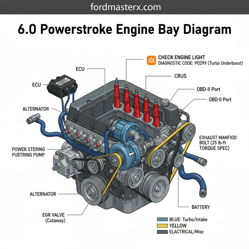
Most 6.0 Powerstroke engine bay diagrams use a standardized numbering system. For example, the number ‘1’ often denotes the Degas Bottle (coolant reservoir), while ‘7’ or ‘8’ usually points to the Secondary Fuel Filter. Always verify the legend on your specific diagram to ensure component accuracy across different truck configurations.
[DIAGRAM_PLACEHOLDER: A detailed top-down view of the 6.0 Powerstroke engine bay. Labels include: 1. Degas Bottle, 2. Air Filter Housing, 3. FICM (ECU), 4. Oil Filter Cap, 5. Secondary Fuel Filter, 6. Alternator, 7. Turbocharger, 8. Glow Plug Control Module, 9. Power Steering Reservoir, 10. Accessory Belt Routing.]
Step-by-Step Guide to Navigating and Maintaining the Engine Bay
To use a 6.0 powerstroke engine bay diagram effectively, you need a systematic approach to component identification. Whether you are replacing a sensor or simply checking fluid levels, follow these steps to master the layout of your diesel engine.
-
✓ Step 1: Identify the Cooling System Foundation
Start by locating the Degas Bottle on the driver-side firewall. This is the heart of your coolant flow. Ensure the cap is the updated 16-psi version. Trace the large radiator hoses to the thermostat housing at the front-top of the engine. Monitoring the pressure here is essential for preventing head gasket failure. -
✓ Step 2: Locate the Control Modules
Find the FICM (Fuel Injection Control Module) on the driver-side valve cover. This unit acts as the primary ECU for your fuel delivery. If your truck struggles to start in the cold, this is the first place to check voltage. Ensure the three large connectors are seated firmly and the mounting brackets are not vibrating excessively. -
✓ Step 3: Inspect the Accessory Belt Drive
Looking at the front of the engine, identify the accessory belt (serpentine belt). The diagram will show the routing through the alternator, water pump, AC compressor, and tensioner. Check for fraying or glazing. If you need to replace the belt, utilize the tensioner’s 1/2-inch drive slot to release pressure. -
✓ Step 4: Map the Fuel and Oil Filtration
On the top-center of the engine, you will see two black caps. The larger one is the oil filter housing, and the smaller one is the secondary fuel filter. Always use a 36mm socket to remove these. Following the diagram’s layout ensures you don’t confuse the two, as they require specific torque specs to avoid cracking the plastic housings. -
✓ Step 5: Access the Diagnostic Interface
While the engine bay contains the hardware, the OBD-II port under the dashboard is your digital gateway to the engine bay’s sensors. Use an OBD-II scanner to pull a diagnostic code when the check engine light appears. This allows you to correlate digital data (like ICP pressure or IPR duty cycle) with the physical components found on your diagram. -
✓ Step 6: Understand the Internal Architecture
While the timing chain is not visible during routine maintenance, the diagram helps you locate the housing at the rear of the block. Unlike many engines, the 6.0 timing chain is at the back, meaning significant engine work is required if issues arise here. Knowing its location prevents you from searching the front of the engine for timing-related components.
When working on the 6.0 Powerstroke, always use a dedicated torque wrench. The torque spec for the oil and fuel filter caps is exactly 25 lb-ft (34 Nm). Over-tightening can lead to air leaks in the fuel system or cracked oil housings, both of which will trigger a check engine light.
Common Issues and Troubleshooting with the Diagram

The 6.0 powerstroke engine bay diagram is your best friend when the check engine light illuminates. One of the most common issues is the “P0611” diagnostic code, which points directly to FICM performance. By using the diagram to locate the FICM, you can perform a voltage test across the internal pins. Another frequent problem involves the EGR cooler and oil cooler. If the “delta” (temperature difference) between your oil and coolant exceeds 15 degrees, the diagram helps you trace the coolant flow to find the blockage in the oil cooler’s tiny passageways.
Warning signs to look for include white smoke (EGR cooler failure), blue smoke (turbo seal failure), or a sudden loss of power (stiction in the injectors or HPOP leak). If you notice coolant spraying from the Degas bottle, your diagram will show you the path from the head gaskets to the cooling system, indicating localized overheating. If you pull a diagnostic code related to the Injection Control Pressure (ICP) sensor, the diagram will show its location—either behind the turbo on early models or on the passenger valve cover on later models.
Never open the cooling system Degas bottle when the engine is hot. The 6.0 runs at high temperatures and pressures; opening the cap can cause severe burns. Use your OBD-II monitor to verify the coolant temperature is below 120°F before performing any inspections.
Best Practices for Engine Bay Maintenance
Maintaining a 6.0 Powerstroke requires more diligence than a standard gasoline engine. The quality of your components is paramount. Always use Motorcraft filters; aftermarket oil filters are often the wrong height and will allow unfiltered oil to bypass the engine, leading to premature wear of the timing chain and bearings.
To keep the engine bay in top shape, perform a “visual sweep” every 5,000 miles. Use your 6.0 powerstroke engine bay diagram to check for signs of “wetness” around the turbo oil feed line and the CAC (Charge Air Cooler) boots. These boots are prone to cracking, which leads to boost leaks and decreased fuel economy. Furthermore, ensure the accessory belt is free of debris. Since the 6.0 uses a heavy-duty cooling fan, a snapped belt can lead to instant overheating.
- ✓ Monitor Your Deltas: Use a digital monitor via the OBD-II port to watch the difference between Oil Temp and Coolant Temp.
- ✓ Electrical Health: Keep your batteries load-tested. Low voltage kills the FICM, which is a costly repair identified on your diagram.
- ✓ Coolant Chemistry: Use only ELC (Extended Life Coolant) to prevent the “silicate dropout” that clogs the oil cooler.
In conclusion, mastering the 6.0 powerstroke engine bay diagram is essential for any owner looking to maximize the lifespan of their vehicle. By identifying key components like the ECU, understanding the path of coolant flow, and monitoring diagnostic codes through the OBD-II system, you can move from basic ownership to expert maintenance. While the 6.0L engine has a reputation for being temperamental, a disciplined approach to understanding its layout and adhering to strict torque specs will ensure your Powerstroke remains a reliable workhorse for years to come.
Frequently Asked Questions
Where is the ECU located?
The ECU on a 6.0 Powerstroke is located on the driver-side fender well, protected by a plastic cover. It communicates with the FICM to control engine timing and fuel delivery. Knowing this location is vital when checking for wiring harness damage or performing diagnostic resets after a repair.
What does this engine bay diagram show?
The 6.0 Powerstroke engine bay diagram illustrates the layout of major components, including the turbocharger, EGR cooler, and degas bottle. It also highlights the positioning of crucial sensors and harness routing, helping DIY mechanics understand how the high-pressure oil system integrates with the fuel system components.
How many connections does the FICM have?
The Fuel Injection Control Module (FICM) features three large electrical connectors that link it to the main engine wiring harness and the ECU. These connections are critical for sending voltage to the injectors. Ensure these are securely seated to prevent common misfire issues or no-start conditions.
What are the symptoms of a bad FICM?
A failing FICM often triggers a check engine light and causes hard starts, especially in cold weather. You may notice a specific diagnostic code related to low circuit voltage when using an OBD-II scanner. Rough idling and decreased power are also common indicators that the module needs testing.
Can I replace the HPOP myself?
Replacing the High-Pressure Oil Pump (HPOP) is a complex DIY task that requires removing the turbo and intake manifold. While possible for experienced mechanics, it involves strict cleanliness and precise torque spec adherence. Use the diagram to identify all necessary removal points before beginning this intensive teardown.
What tools do I need for engine diagnostics?
You will need a basic socket set, a torque wrench for meeting every specific torque spec, and an OBD-II scan tool. A digital multimeter is also essential for testing voltage at the FICM or ECU. These tools allow you to read a diagnostic code and verify electrical health.


