6.0 Powerstroke Alternator Wiring Diagram: Easy Setup Guide
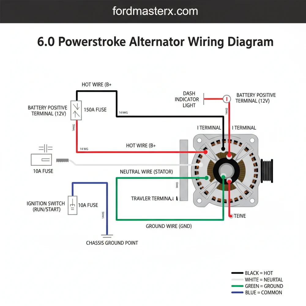
A 6.0 Powerstroke alternator wiring diagram illustrates the circuit between the charging unit and the batteries. It features a heavy hot wire for current and a ground wire for the return path. While DC systems lack a traditional neutral wire, the chassis ground serves this role. The regulator plug acts like a traveler wire, connecting the PCM common terminal to the alternator.
📌 Key Takeaways
- Identifies the relationship between the alternator, PCM, and dual battery setup
- The B+ output post is the most critical power transfer point
- Always disconnect both batteries before touching the alternator wiring to prevent shorts
- Ensures proper voltage regulation to protect sensitive fuel injectors (FICM)
- Use this diagram when installing high-output alternators or fixing charging faults
The 6.0L Powerstroke diesel engine, found in Ford Super Duty trucks from 2003 to 2007, is a powerhouse known for its towing capabilities and durability. However, it is equally famous for being incredibly demanding on its electrical system. Between the high-amperage glow plugs and the sensitive Fuel Injection Control Module (FICM), the alternator and its associated wiring are the lifeblood of the vehicle. Understanding the 6.0 Powerstroke alternator wiring diagram is not just a matter of academic interest; it is a vital skill for any DIY enthusiast looking to maintain reliability or upgrade to a high-output charging system. Because the FICM requires a steady supply of at least 45 to 48 volts (derived from the 12V system), any drop in alternator performance due to frayed wiring or poor connections can lead to expensive engine component failures.
Main Components and Features of the Wiring System
The charging system on the 6.0 Powerstroke is relatively straightforward but contains specific features that differ slightly from standard gasoline engines. The system generally consists of the alternator (with an internal voltage regulator), the battery bank (dual batteries connected in parallel), the PCM (Powertrain Control Module), and the instrument cluster charging indicator. Depending on the specific configuration of your truck, you may have a single high-output alternator or a dual-alternator setup, which was common in “Ambulance Package” trucks or those equipped for heavy snowplow use.
The primary components of the wiring diagram include:
- The B+ Terminal: This is the large stud on the back of the alternator. It is connected directly to the passenger-side battery via a heavy-gauge wire (usually 6-gauge or 4-gauge stock). This wire carries the bulk of the charging current.
- The Regulator Plug (C1106): This is a 3-pin connector that plugs into the side of the alternator. While there are three slots, typically only two wires are utilized in a standard 6.0 setup.
- The Sensing Wire (Orange with Light Blue Stripe): Located at Pin 1 of the 3-pin plug, this wire tells the internal regulator how much voltage is actually present in the system.
- The Ignition/Turn-on Wire (Light Green with Red Stripe): Located at Pin 3, this wire receives a signal when the key is in the “ON” position. It “wakes up” the alternator and initiates the charging process. This wire also controls the battery light on your dashboard.
- Fusible Links: Ford incorporates fusible links into the main B+ harness. These are sacrificial sections of wire designed to melt and break the circuit in the event of a massive short, preventing a vehicle fire.
How to Use and Read the Wiring Diagram

Reading a 6.0 Powerstroke wiring diagram requires an understanding of the path the electricity takes from the alternator back to the batteries. When you look at a schematic for this vehicle, you will notice that the wiring is split into the “Charging Circuit” and the “Control Circuit.” For a DIYer, the most important part is identifying the colors and the pinouts on the 3-pin regulator connector.
1. The High-Current Path (B+): On the diagram, you will see a thick line representing the Red or Black/Orange wire coming off the B+ terminal. This wire travels from the alternator, across the front of the engine, and connects to the positive terminal of the passenger-side battery. In dual alternator setups, the secondary alternator (mounted lower on the engine) has its own B+ wire that merges into the main harness.
2. The Regulator Connector Pinout:
- Pin 1 (A-Terminal): The Orange/Light Blue wire. This is the “Battery Sense” circuit. It usually tracks back to the battery or a junction box. It monitors the voltage levels so the regulator knows if it needs to increase or decrease output.
- Pin 2 (S-Terminal): This is often empty on many 6.0 diagrams or used as a stator signal for certain aftermarket tachometers. In standard OEM configurations, you will see a dummy plug or an empty cavity here.
- Pin 3 (I-Terminal): The Light Green/Red wire. This is the “Indicator” circuit. It goes through the central junction box and links to the instrument cluster. If this wire is broken, your alternator will not “excite” or start charging, even if the alternator itself is brand new.
To read the diagram effectively, use a digital multimeter. When the key is on, you should see battery voltage at Pin 3. If you see 0V here, the alternator will never turn on. Similarly, Pin 1 should always show battery voltage, as it is the sensing line directly linked to the power source.
Essential Tips for DIY Enthusiasts
Working on the 6.0 Powerstroke electrical system requires attention to detail. Because this engine creates a significant amount of heat and vibration, the wiring is prone to “chaffing” (rubbing through the insulation). Here are some practical tips for handling the wiring:
- Check for Chaffing: The wiring harness for the alternator often rubs against the intake manifold or the cooling fan shroud. Inspect the corrugated loom for signs of wear. If the Light Green/Red wire shorts to the ground, it can blow fuses or cause the battery light to stay on permanently.
- Voltage Drop Testing: Don’t just check for continuity. Perform a voltage drop test on the main B+ cable. With the engine running and headlights on, measure the voltage between the alternator output stud and the positive battery terminal. If the difference is more than 0.5V, your wiring has internal resistance and needs replacement.
- Connector Maintenance: The 3-pin plug is notorious for getting brittle due to heat cycles. If the locking tab is broken, the connector can vibrate loose, leading to intermittent charging. Replacement pigtails are inexpensive and should be soldered into the harness rather than using crimp connectors for a more reliable repair.
- Grounding is Key: The alternator grounds through its casing to the engine block. Ensure the mounting bolts are clean and torqued properly. A layer of corrosion between the alternator bracket and the engine can drop your charging efficiency significantly.
Troubleshooting Common Wiring Issues
If your 6.0 Powerstroke is not charging, do not immediately assume the alternator is dead. Often, the fault lies within the wiring. Use the following steps to troubleshoot using the wiring diagram as your guide:
Step 1: Check the Fuses. Before tearing into the harness, check the under-dash fuse panel. Specifically, look for the fuse associated with the instrument cluster and the charging system (often Fuse 2.45 or similar depending on the year). If the “Battery Light” on the dash does not illuminate when you turn the key to the “ON” position (before cranking), the alternator will not receive the “wake-up” signal from the Light Green/Red wire.
Step 2: Measure Voltage at the B+ Stud. With the engine running, use a multimeter to check the voltage at the back of the alternator. It should be between 13.5V and 14.4V. Then, check the voltage at the batteries. If the alternator stud shows 14V but the batteries show 12.5V, you have a blown fusible link or a compromised B+ cable.
Step 3: Test the “I” and “A” Terminals. Unplug the 3-pin connector. With the key in the “OFF” position, test the Orange/Light Blue wire; it should have battery voltage. Turn the key to the “ON” position and test the Light Green/Red wire; it should also have voltage (though sometimes slightly lower than battery voltage). If either wire is dead, you have a break in the harness or a blown fuse upstream.
Step 4: The “Battery Light” Symptom. If the battery light stays on while the engine is running, the PCM or cluster has detected that the voltage output does not match the desired setpoint. On the 6.0, this can sometimes be caused by a faulty sensing wire (Orange/Light Blue) having high resistance, tricking the regulator into overcharging or undercharging.
By understanding the specific wire colors and the functions of the 3-pin connector, DIYers can save hundreds of dollars in “parts cannon” repairs. The 6.0 Powerstroke is a sensitive machine, but with a solid grasp of its alternator wiring diagram, you can ensure your truck has the electrical stamina to handle any job.
Step-by-Step Guide to Understanding the 6.0 Powerstroke Alternator Wiring Diagram: Easy Setup Guide
Identify components – Locate the alternator, the dual batteries, and the PCM signal harness.
Locate the B+ terminal – Find the heavy-gauge hot wire attached to the rear of the alternator.
Understand the plug – Disconnect the regulator harness to inspect the traveler wire pins for corrosion.
Connect the ground – Ensure the alternator mounting bolts are clean, as they serve as the common terminal for grounding.
Verify voltage – Use a multimeter to check for 13.5 to 14.5 volts while the engine is running.
Complete the circuit – Re-secure all protective boots over the hot wire to prevent accidental grounding against the engine.
Frequently Asked Questions
Where is the 6.0 Powerstroke alternator located?
The alternator on a 6.0 Powerstroke diesel is conveniently located at the top-center or slightly toward the passenger side of the engine bay. It is mounted on the main accessory bracket, making it one of the easiest components to access for testing, wiring repairs, or complete replacement.
What does a 6.0 Powerstroke alternator wiring diagram show?
This diagram displays the path of the high-amperage hot wire to the batteries and the small-gauge wires in the regulator connector. It shows how the PCM monitors charging status and how the dash battery light is triggered, detailing every connection point from the common terminal to the frame ground.
How many wires does the 6.0 Powerstroke alternator have?
The system uses a main heavy-gauge B+ hot wire and a three-pin harness connector. Although three slots exist in the plug, some configurations only utilize two. These wires manage voltage sensing and the dashboard warning light. The alternator housing itself typically serves as the primary connection to the ground wire.
What are the symptoms of a bad 6.0 Powerstroke alternator?
Common symptoms include a battery light on the dashboard, dimming headlights, or a failing Fuel Injection Control Module (FICM) due to low voltage. If the hot wire or traveler wire signals are interrupted, the batteries will not charge, eventually leading to a no-start condition and potential engine stalling.
Can I replace 6.0 Powerstroke alternator wiring myself?
Yes, replacing the wiring or the alternator is a straightforward DIY task. By following a wiring diagram, you can identify which leads are the hot wire and which are the signal wires. Ensure all connections are tight and corrosion-free to maintain the high amperage required by the diesel glow plugs.
What tools do I need for alternator wiring repair?
You will need a 1/2-inch drive breaker bar to release the belt tensioner, a set of sockets (10mm, 12mm, and 13mm are common), and a digital multimeter. The multimeter is essential for verifying that the hot wire is receiving battery voltage and that the ground wire has continuity.


