4 Pin Brake Light Switch Diagram: Easy Setup Guide
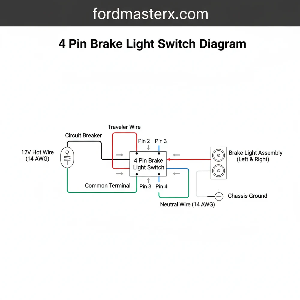
A 4 pin brake light switch diagram shows two separate circuits. One pair of pins handles the brake lights, connecting the hot wire to the bulb. The other pair typically signals the cruise control or ECU. Identifying the common terminal and traveler wire ensures the signal flows correctly when the pedal is pressed.
📌 Key Takeaways
- Identifies the dual-circuit nature of the four-pin switch
- Highlights the importance of the internal plunger mechanism
- Emphasizes disconnecting the battery for electrical safety
- Recommends using a multimeter for pin identification
- Explains how to use the diagram for brake and cruise control repairs
Finding an accurate 4 pin brake light switch diagram is the most critical first step when diagnosing lighting failures or cruise control malfunctions in your vehicle. Unlike older two-pin systems that simply complete a circuit to illuminate bulbs, a four-pin configuration serves a dual
Understanding the 4 Pin Brake Light Switch Diagram
When you look at a 4 pin brake light switch diagram, you are essentially looking at two separate switches housed within a single plastic casing. These switches are typically designed to operate in opposite states. One circuit is “Normally Open” (NO), meaning the connection is broken until you press the brake pedal. The other circuit is “Normally Closed” (NC), meaning the connection is constant until the pedal is depressed, at which point it interrupts the signal.
The diagram identifies four distinct terminals. The first pair usually handles the high-voltage load required to power the brake lamps. This involves a hot wire coming from the fuse box and a traveler wire that sends the current to the rear of the vehicle. The second pair of pins is dedicated to logic signals. When you tap the brakes, this circuit opens, sending a signal to the vehicle’s computer to disengage the cruise control or unlock the shift interlock solenoid.
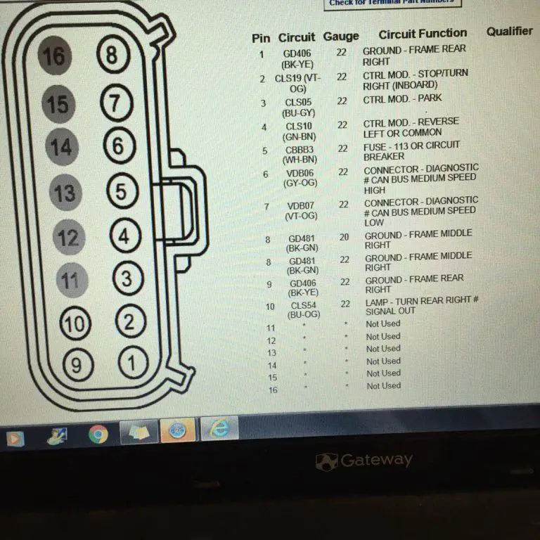
Visualizing the diagram requires looking at the pinout from the perspective of the connector face. You will often see a common terminal or a specific orientation indicated by a notch on the plastic housing. In many professional diagrams, the pins are numbered 1 through 4. Pins 1 and 2 are frequently the heavy-duty set for the lights, while Pins 3 and 4 handle the low-current sensor data. It is important to note that wire colors can vary significantly between manufacturers, but the functional logic remains consistent across most automotive standards.
Step-by-Step Guide to Installation and Interpretation

Interpreting a 4 pin brake light switch diagram and translating it to the physical wires under your dashboard requires a methodical approach. Follow these steps to ensure a professional-grade installation.
Before beginning, always verify the specific wire gauge used in your vehicle. Most brake light circuits use 14 or 16-gauge wire to handle the current without overheating, while sensor wires may be thinner 18 or 20-gauge.
- Safety First: Disconnect the Battery – Before touching any electrical components, disconnect the negative battery terminal. This prevents accidental short circuits that could blow expensive fuses or damage the PCM.
- Locate and Inspect the Connector – Crawl into the driver’s side footwell and find the switch mounted near the top of the brake pedal arm. Unplug the harness and inspect the pins for corrosion. Compare the physical orientation of the pins to your wiring diagram to ensure they match.
- Identify the Hot Wire – Using a digital multimeter set to DC voltage, reconnect the battery briefly to test the wires. One wire should show 12V constant power even when the pedal is not touched. This is your primary hot wire. In some diagrams, this may be connected to a brass screw or a specific colored terminal in the harness.
- Distinguish the Traveler Wire – The traveler wire is the one that remains “dead” (0V) until the brake pedal is pushed. Once the switch completes the circuit, this wire carries the voltage to the brake lights. Identify this on your diagram to ensure you don’t cross it with the cruise control circuit.
- Verify the Sensor Circuit – The remaining two pins are for the cruise control or PCM signal. One will typically show a lower voltage or a logic-level signal. In many modern vehicles, this acts like a neutral wire in a household circuit by completing a path to ground or providing a steady reference voltage that the computer monitors.
- Mount the New Switch – Insert the switch into the bracket. Most 4-pin switches require a “twist-lock” motion or a specific depth adjustment. If the switch is too close to the pedal, the lights will stay on; if it is too far, they won’t trigger at all.
- Connect and Test – Snap the 4-pin connector back into place. Reconnect your battery and perform a functional test. Have a helper stand behind the car to confirm the brake lights illuminate, and then test your cruise control on a clear road to ensure it cancels when the pedal is tapped.
Never bypass a 4-pin switch by jumping the wires together. Doing so can send 12V directly into the PCM sensor circuit, which is only designed for low voltage, potentially resulting in a fried engine control unit.
Common Issues and Troubleshooting

Even with a perfect 4 pin brake light switch diagram, problems can arise. The most frequent issue is a “stuck” switch. Because the switch has two internal circuits, you might encounter a scenario where your brake lights work perfectly, but your cruise control won’t engage. This indicates that the NC (Normally Closed) side of the switch has failed while the NO (Normally Open) side remains functional.
Another common problem involves the ground wire or the common terminal. If the connection to the frame is weak, the voltage may drop significantly before reaching the bulbs, causing dim lights. Use your diagram to trace the ground path. If the diagram shows a shared ground for both circuits, a single loose bolt can cause multiple phantom issues, such as the brake lights flickering when you hit a bump or the gear shifter getting stuck in “Park.”
If you notice that your brake lights stay on permanently, the switch might have slipped out of its bracket, or the plastic “stop” on the brake pedal arm may have broken. Check the diagram to see if the switch relies on a “ground-side switch” or “power-side switch” logic, as this will change how you test for shorts using your multimeter.
Tips and Best Practices for Wiring Success
When working with a 4 pin brake light switch, precision is your best friend. Professional technicians always recommend checking the condition of the pins inside the harness. Over time, heat and vibration can cause the female terminals to spread apart, leading to an intermittent connection that a diagram won’t show.
Apply a small amount of dielectric grease to the connector pins before reassembling. This prevents moisture from causing corrosion and ensures the voltage remains stable across the common terminal for years to come.
- ✓ Match the Gauge: Always use the factory-recommended wire gauge if you need to repair a pigtail. Using a wire that is too thin can cause a fire hazard.
- ✓ Check Fuses First: Before replacing the switch, check the “Stop” and “Cruise” fuses in the cabin fuse box. A blown fuse is often a symptom of a short in the traveler wire.
- ✓ Quality Matters: Avoid the cheapest “no-name” switches. The internal springs in a 4-pin switch are under constant tension; high-quality components use better alloys for the brass screw contacts and internal plates.
- ✓ Clear Codes: In many modern vehicles, a faulty brake switch will trigger a Check Engine Light (CEL) or an ABS warning. After installation, you may need an OBD-II scanner to clear these stored codes.
In summary, mastering the 4 pin brake light switch diagram allows you to take control of your vehicle’s safety and electronic communication systems. By identifying the hot wire, managing the traveler wire, and ensuring the sensor circuits are correctly routed to the PCM, you can resolve complex issues that often baffle amateur mechanics. Always prioritize high-quality parts and double-check your terminal connections to ensure your brake lights and cruise control operate flawlessly for the long haul.
Frequently Asked Questions
Where is the 4 pin brake light switch located?
The 4 pin brake light switch is located directly above the brake pedal arm. Look for a small plastic component with a plunger that rests against the pedal. It is usually mounted on a bracket under the dashboard, making it accessible after removing the lower trim panel.
What does a 4 pin brake light switch diagram show?
This diagram illustrates the pinout for the switch, showing how the hot wire connects to the light circuit. It clarifies how the traveler wire sends signals to the cruise control system. It helps identify which pins complete the circuit when the pedal is depressed versus when it is released.
How many connections does a 4 pin brake light switch have?
A 4 pin brake light switch has four electrical connections. Two pins form the primary brake light circuit, while the other two pins are for secondary functions like cruise control deactivation or shift interlock. Each pair operates independently to ensure the vehicle responds correctly to pedal input.
What are the symptoms of a bad 4 pin brake light switch?
A bad switch causes brake lights to stay on constantly or not illuminate at all. You might also experience cruise control failure or the inability to shift out of ‘Park.’ If the traveler wire doesn’t receive signal, the vehicle’s computer won’t know the brakes are being applied.
Can I replace a 4 pin brake light switch myself?
Yes, replacing this switch is a common DIY task. It usually involves a simple twist-and-pull or a single retaining nut. Following a 4 pin brake light switch diagram ensures you align the connector correctly. However, ensure the ground wire and power sources are secure for proper operation.
What tools do I need for this wiring task?
You will need a basic socket set or wrench to remove the mounting nut, a flashlight for visibility under the dash, and a multimeter. The multimeter is essential for testing the common terminal and verifying that the hot wire and neutral wire connections are functioning as intended.