3 Wire Wiper Motor Wiring Diagram: Easy Setup Guide
A 3 wire wiper motor wiring diagram typically consists of a hot wire for power, a ground wire for the circuit return, and a traveler wire for speed or park functions. One lead connects to the common terminal of the switch, allowing the motor to receive current and operate effectively.
📌 Key Takeaways
- Identifies the power flow between the ignition switch and the wiper motor
- Helps locate the common terminal to prevent electrical short circuits
- Emphasizes the importance of a clean ground wire for consistent motor speed
- Provides a reference for testing voltage on the traveler wire during park cycles
- Essential for replacing aftermarket motors or repairing classic car harnesses
Dealing with a faulty windshield wiper system can be frustrating, especially when you are faced with a tangle of aging wires or a motor that refuses to park correctly. Whether you are restoring a classic vehicle, upgrading a marine vessel, or troubleshooting a custom project, understanding a 3 wire wiper motor wiring diagram is essential for a safe and functional installation. Having the correct diagram ensures that you do not accidentally short the circuit or damage the internal park switch. In this guide, you will learn how to identify each terminal, determine the proper wire gauge for your voltage requirements, and successfully wire your motor for reliable performance in any weather.
Decoding the 3 Wire Wiper Motor Wiring Diagram
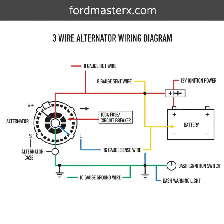
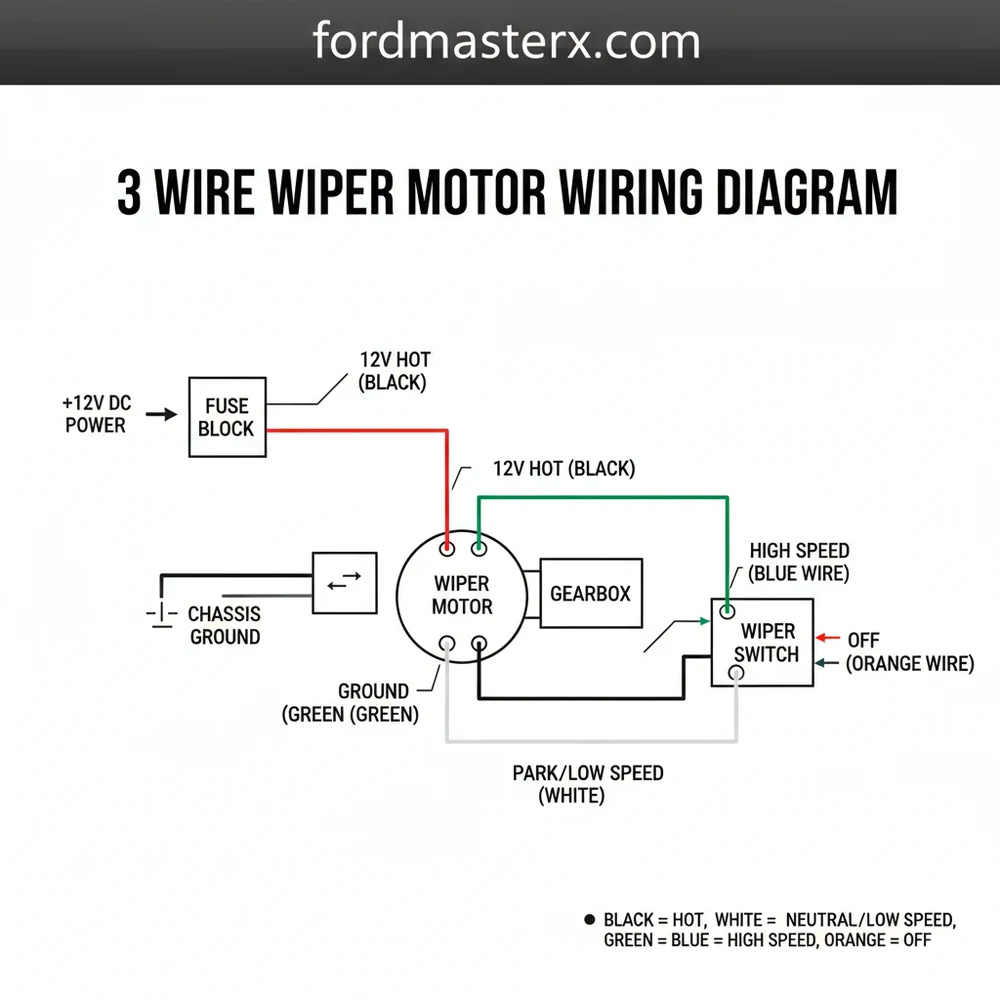
The 3 wire wiper motor wiring diagram is a visual representation of the electrical path required to operate the motor’s low-speed, high-speed, and self-parking functions. Unlike modern multi-pin connectors, the three-wire system relies on a simpler configuration where each wire serves a specific, vital purpose. In most standard DC configurations, these wires represent the low-speed power, the high-speed power, and the park circuit (often referred to as the traveler wire).
Understanding the layout begins with the common terminal. In many wiper motors, the motor housing itself acts as the ground wire connection, but in isolated systems, one of the three wires may serve as a dedicated ground or common return. The diagram typically shows a hot wire coming from the battery through a fuse and then to the wiper switch. From the switch, the power is directed to either the low-speed or high-speed terminal on the motor.
+——————————————+
| WIPER SWITCH (3-POSITION) |
| [BATT]—-(FUSE)—-[L] [H] [P] |
+———–|———–|—-|—-|——–+
| | | |
| (LOW) wire| | (PARK) traveler wire
| | | |
+——-V———–V—-V—-V——–+
| WIPER MOTOR |
| (1) Low Speed Terminal |
| (2) High Speed Terminal |
| (3) Park/Common Terminal |
| [GROUND] — Motor Case/Brass Screw |
+————————————–+
Figure 1: Typical 3-wire DC wiper motor circuit illustrating power flow from the switch to the motor terminals.
The visual breakdown often includes color-coding. While colors can vary by manufacturer, a common standard involves a Red wire for high speed, a Blue or White wire for low speed, and a Yellow or Green traveler wire for the park function. The internal park switch is a mechanical contact that keeps the motor energized even after you turn the switch “off,” until the blades reach the bottom of the windshield. At that point, the circuit is broken, and the motor stops. If your motor has a brass screw located on the exterior housing, this is usually the primary chassis ground point.
In 3-wire systems, the “traveler wire” is what allows the wipers to finish their sweep after you turn the switch off. It provides a constant hot feed to the internal limit switch until the “Park” position is reached.
Step-by-Step Installation and Wiring Guide
Reading a 3 wire wiper motor wiring diagram is the first step, but the physical installation requires a methodical approach to ensure longevity and safety. Follow these steps to wire your motor correctly.
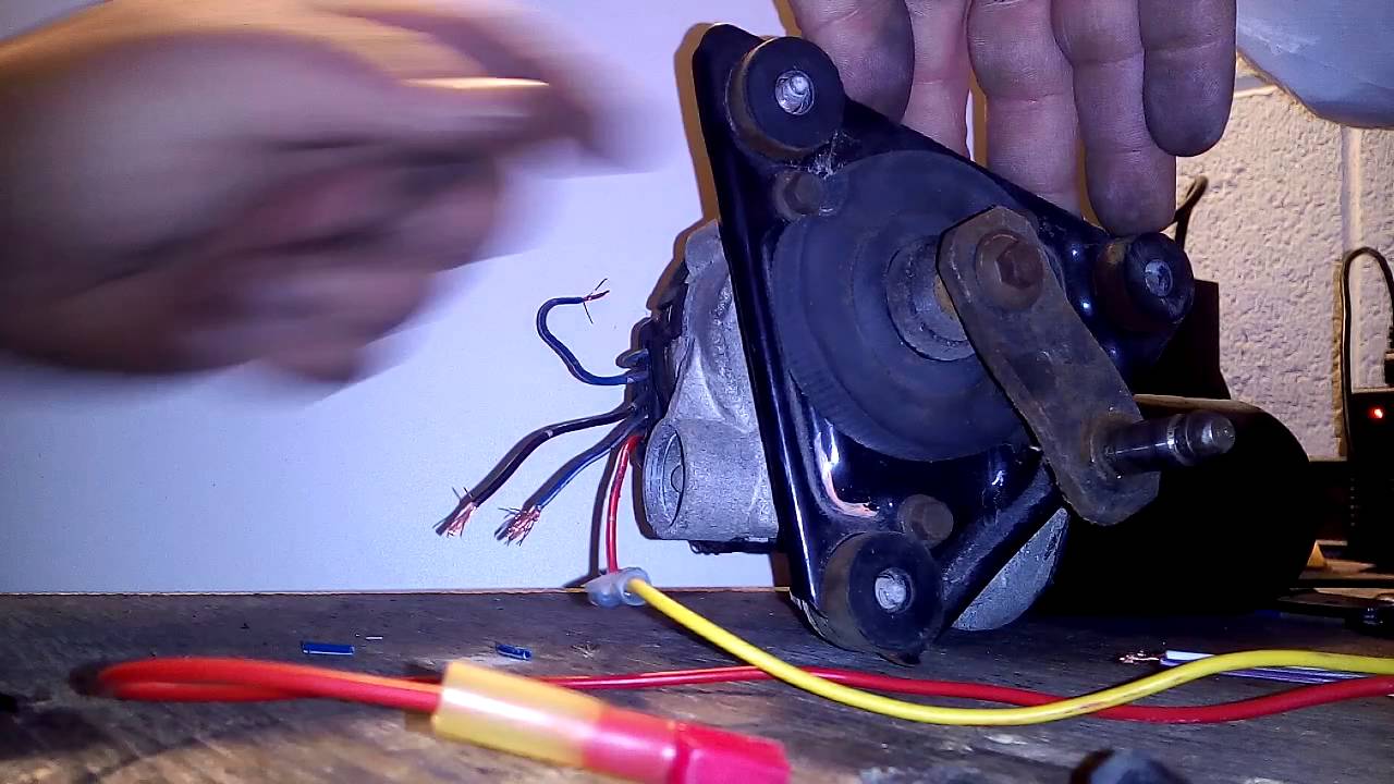
Step 1: Identify Your Terminals and Tools
Before starting, gather a digital multimeter, wire strippers, heat shrink tubing, and a crimping tool. Inspect the motor to locate the terminals. If they are not labeled, look for a brass screw on the casing which usually indicates the ground. Use your multimeter in continuity mode to check which terminal connects to the internal brushes. One terminal will show lower resistance (high speed) and another will show slightly higher resistance (low speed).
Step 2: Establish a Solid Ground
A common failure point in wiper systems is a poor ground wire connection. If the motor is mounted to a painted metal surface, the motor may not ground properly through its mounting bolts. Run a dedicated 14 or 16 gauge wire from the brass screw on the motor housing directly to the negative terminal of the battery or a known clean chassis ground point. This ensures consistent voltage and prevents the motor from running slowly or overheating.
Step 3: Connect the Constant Hot Wire
The “Park” function requires power even when the ignition or switch is off (or in the off position). Identify the terminal on your motor intended for the parking circuit. Connect this to a fused hot wire that has power whenever the ignition is in the “ON” or “ACC” position. This is the traveler wire that carries current to the internal cam switch.
Step 4: Wire the Low and High Speed Circuits
Locate the low and high-speed outputs on your wiper switch. Using the appropriate gauge wire, run a line from the “Low” switch terminal to the corresponding motor terminal. Repeat this for the “High” speed terminal. In some 3-wire motors, high speed is achieved by bypassing a portion of the internal windings, so ensuring these are not swapped is critical for motor health.
Step 5: Inspect the Neutral Wire or Return Path
In some marine or specialized industrial applications, you may encounter a setup that refers to a neutral wire. While DC systems typically use “positive” and “negative,” the neutral wire in this context often refers to the common return path in a dual-voltage or AC-converted system. Ensure that the common terminal is correctly identified on your 3 wire wiper motor wiring diagram to avoid a direct short.
Step 6: Test the Self-Parking Mechanism
With the wires temporarily connected, turn the wiper switch to the “Low” position. Let the wipers move across the glass (ensure the glass is wet to prevent scratching). Turn the switch to the “Off” position. The wipers should continue to move until they reach the base of the windshield. If they stop immediately where you turned them off, the traveler wire or the park terminal is likely miswired or lacking constant voltage.
Never test wiper motors on a dry windshield. The friction can cause the motor to draw excessive current, potentially blowing the fuse or damaging the internal gears before you even finish the installation.
Common Issues & Troubleshooting

Even with a perfect 3 wire wiper motor wiring diagram, issues can arise during the installation process or after years of use. One of the most frequent problems is a motor that runs but will not park. This usually indicates that the traveler wire has lost its constant voltage source or the internal contact plate inside the motor is corroded.
Another common issue is “intermittent stopping,” where the motor stops at random intervals. This is often caused by a loose common terminal or a ground wire that is vibrating loose from the brass screw. Use your multimeter to check the voltage at the motor while it is running; if the voltage drops significantly, your wire gauge may be too thin for the length of the run, or you have a high-resistance connection.
If the motor hums but does not move, it may be a mechanical blockage in the linkage or a seized motor shaft. However, from a wiring perspective, this could also mean the high and low speed wires are energized simultaneously due to a faulty switch, causing the magnetic fields to fight each other.
- ✓ Wipers won’t turn off: Check if the park switch is stuck or if the traveler wire is shorted.
- ✓ Only one speed works: Inspect the switch terminals and the specific speed wire for continuity.
- ✓ Motor runs hot: Ensure the ground wire is sufficient and the voltage is within the 12V-14V range.
Tips & Best Practices for Wiper Wiring
To ensure your 3 wire wiper motor wiring diagram implementation lasts for the life of the vehicle, follow these professional best practices. First, always use automotive-grade primary wire. For most wiper motors, 16 gauge wire is sufficient for short runs, but if the motor is located far from the power source (such as in a large boat or RV), stepping up to 14 gauge wire will help prevent voltage drop.
Apply a small amount of dielectric grease to all terminal connections and the brass screw ground. This prevents moisture from causing oxidation, which is the leading cause of “ghost” electrical issues in wiper systems.
When making connections, soldering and using adhesive-lined heat shrink is the gold standard for durability. If you prefer crimp connectors, ensure you use the correct tool to create a “cold weld” connection that won’t pull apart under vibration. Furthermore, always install an in-line fuse as close to the power source as possible. A 10-amp or 15-amp fuse is standard for most 3-wire motors, but consult your specific motor’s manual for exact specifications.
Maintenance is also key. Periodically check the traveler wire for brittle insulation, especially where it passes through firewalls or bulkheads. If you are replacing an old motor, it is often worth replacing the wiper switch at the same time, as internal switch wear can mimic motor failure. By following these guidelines and accurately referencing your 3 wire wiper motor wiring diagram, you can ensure clear visibility and safe driving for years to come.
Frequently Asked Questions
Where is the wiper motor located?
The wiper motor is usually located on the firewall or within the cowl area beneath the windshield. It is positioned behind the engine block to protect it from road debris while remaining accessible for maintenance. You may need to remove plastic trim or the wiper arms to access it.
What does a 3 wire wiper motor wiring diagram show?
This diagram illustrates the electrical path from the battery and switch to the motor. It highlights how the hot wire provides energy, while the traveler wire and ground wire complete the circuit. Understanding these paths ensures the motor operates at the correct speed and returns to the park position.
How many connections does a 3 wire wiper motor have?
A 3 wire wiper motor features three primary connections: a positive power feed (hot wire), a chassis ground wire, and a signal or traveler wire. These connections link the motor to the common terminal on the wiper switch, facilitating basic low and high-speed operations or park features.
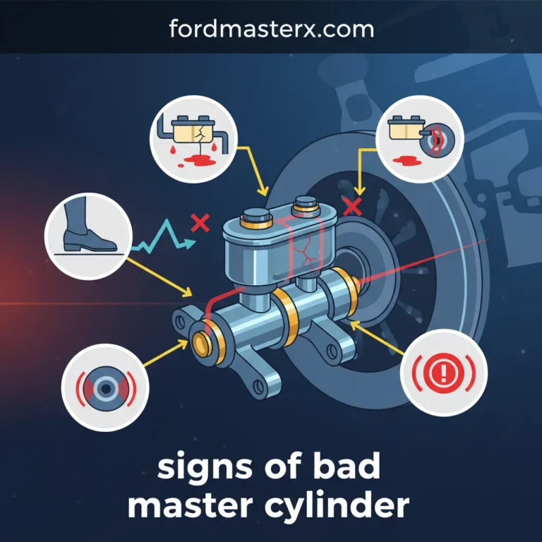
What are the symptoms of a bad wiper motor?
Common symptoms include wipers moving slower than usual, getting stuck mid-stroke, or failing to move at all. You might also hear humming noises without movement. If the traveler wire is faulty, the wipers may not return to their starting position once the switch is turned off.
Can I replace a wiper motor myself?
Yes, replacing a wiper motor is a common DIY task that requires basic hand tools. By following a 3 wire wiper motor wiring diagram, you can safely disconnect the old unit and wire the new one. Ensure the battery is disconnected before starting to prevent any electrical shorts.
What tools do I need for this task?
You will need a socket set and wrenches to remove the mounting bolts, a flathead screwdriver for prying clips, and a multimeter to test for voltage. Wire strippers and electrical tape are also useful if you need to repair the harness or secure the traveler wire.