2012 F150 Radio Wiring Diagram: Easy Setup Guide
The 2012 f150 radio wiring diagram identifies the battery 12V (hot wire) and ground wire connections. While automotive systems don’t use a neutral wire or traveler wire like home AC circuits, identifying the common terminal on the harness ensures a proper return path for your aftermarket stereo installation and speakers.
📌 Key Takeaways
- Identifies wire colors for power, ground, and speakers
- Most important component to identify is the constant 12V hot wire
- Always disconnect the battery to prevent short circuits during wiring
- Use a vehicle-specific harness to avoid cutting factory wires
- Essential for installing aftermarket head units or amplifiers
When you are looking to upgrade the factory sound system in your truck, having an accurate 2012 f150 radio wiring diagram is the difference between a seamless installation and a permanent electrical headache. The 2012 Ford F-150 remains a popular platform for DIY audio enthusiasts, but its electrical architecture can be complex due to the integration of SYNC systems and steering wheel controls. By understanding the specific pinouts and color codes, you can ensure that your new head unit receives the correct voltage and sends clear signals to your speakers. This article provides a comprehensive breakdown of the wiring harness, identifies critical connection points, and guides you through the process of mapping your aftermarket harness to the factory plugs.
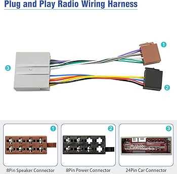
Most 2012 F-150 models utilize a 24-pin main connector for primary power and speaker outputs. If your truck is equipped with the Sony Premium Sound System, you will also have an auxiliary 16-pin connector that handles the external amplifier and subwoofer signals.
Detailed Main Diagram Description and Pin Identification
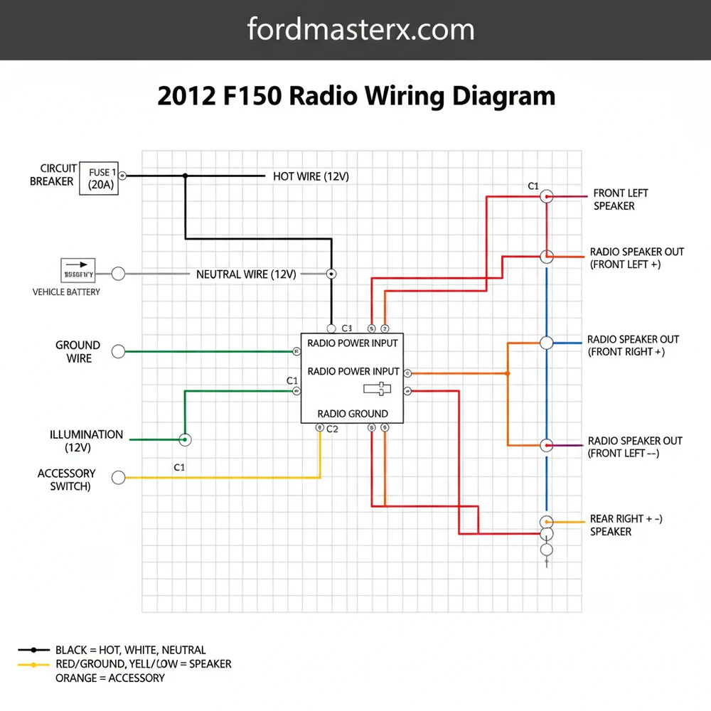
The wiring architecture of the 2012 F-150 is centralized around the main radio chassis. When you look at the back of the factory unit, you will typically see two or three distinct harness sockets. The largest is the primary 24-pin connector. This connector serves as the lifeblood of the system, carrying the hot wire for constant power, the ground wire for circuit completion, and the eight primary leads for the cabin speakers. Unlike a household circuit where you might look for a brass screw or a neutral wire, automotive systems rely on colored insulation and pin position within a plastic housing.
In a standard non-Sony system, the diagram layout follows a specific logic. The top row of pins generally handles power and ground, while the bottom row focuses on speaker polarity. For instance, the constant 12V power source, often referred to as the hot wire, is typically found at Pin 1. This wire ensures your radio retains its clock settings and preset stations when the ignition is turned off. The ground wire, which is the equivalent of the return path in a DC circuit, is usually Black with a Blue or Green stripe. It is essential that this wire is secured to a clean metal surface or the corresponding harness pin to prevent ground loops or static.
This visual representation shows the 24-pin harness face. Pin 1 (Top Left): Yellow/Red (12V Constant). Pin 13 (Bottom Left): Black/Blue (Ground). Middle Pins: Speaker Pairs (White, Gray, Green, Purple).
When interpreting the diagram, you must also account for the gauge of the wire. Power and ground wires are usually a thicker 16 or 18 gauge to handle the current draw, whereas speaker wires and signal wires for the dimming circuit might be a thinner 20 or 22 gauge. If your truck has steering wheel controls, these signals are usually transmitted via a dedicated pair of wires in the secondary harness. While home electrical systems might use a traveler wire for three-way switching, automotive diagrams use “Can-Bus” or “Resistive” signals to communicate between the buttons and the head unit.
Step-by-Step Guide to Interpreting and Installing Your Radio

Navigating a 2012 f150 radio wiring diagram requires a methodical approach. Before you begin cutting or crimping, you need to gather the right tools and prepare the workspace. You will need a digital multimeter to verify voltage, wire strippers, a crimping tool or soldering iron, and high-quality heat shrink tubing.
- ✓ Step 1: Disconnect the Negative Battery Cable. This is a critical safety step to prevent blowing the radio fuse or damaging the truck’s Body Control Module (BCM).
- ✓ Step 2: Remove the Dashboard Bezel. Carefully pry the plastic trim surrounding the radio using a non-marring tool. Remove the 7mm bolts securing the factory head unit.
- ✓ Step 3: Identify the Harness Pins. Use your wiring diagram to locate the “hot wire” (constant 12V) and the “switched wire” (12V accessory). In many F-150s, the accessory power is actually controlled by the data bus, meaning you may need a specialized harness adapter to
- ✓ Step 4: Map the Speaker Polarity. The diagram will list colors such as White/Brown and White/Black for the front left speaker. Ensure the positive and negative leads are matched correctly to prevent “out of phase” audio, which results in poor bass response.
- ✓ Step 5: Test the Ground. Verify the ground wire has continuity to the chassis. A common terminal point for multiple grounds can sometimes cause interference, so ensure your radio ground is solid.
- ✓ Step 6: Connect the Aftermarket Harness. Match the wires from your new radio to the adapter harness. Use the diagram to confirm that no wires are crossed. Note that there is no “neutral wire” or “brass screw” here as you would find in a wall outlet; everything is color-coded to the EIA standard.
- ✓ Step 7: Final Voltage Check. Before sliding the radio into the dash, reconnect the battery and use your multimeter to check the voltage at the harness. You should see roughly 12.6V at the constant pin.
Do not attempt to tap into wires blindly. The 2012 F-150 uses a sensitive CAN-bus system. Probing the wrong wire with a test light can trigger airbag codes or damage the instrument cluster. Always use a high-impedance digital multimeter for testing.
Common Issues & Troubleshooting
Even with a perfect 2012 f150 radio wiring diagram, you may encounter obstacles during the installation. One of the most frequent issues is the “no power” condition. If the radio fails to turn on, the first place to look is the fuse box located in the passenger-side kick panel. Often, the accessory circuit is confused with the constant hot wire. If your radio loses its memory every time you turn off the truck, you have likely swapped these two wires.
Another common problem is speaker hiss or “alternator whine.” This is frequently caused by a poor ground wire connection. In automotive electrical systems, the chassis acts as the common terminal for the negative side of the battery. If your ground wire is loose or connected to a painted surface, it can pick up electrical noise. Ensure your ground is connected to a clean, unpainted bolt. Additionally, if you have the Sony system and hear no sound after installation, it is likely because the remote turn-on wire for the factory amplifier has not been connected to the Blue/White wire of your new radio.
If your truck has a factory backup camera that displays in the rearview mirror, it won’t be affected by the radio wiring. However, if the camera displays on the factory screen, you will need a specific data retention module to port that video signal to your new aftermarket screen.
Tips & Best Practices for Audio Installation
To achieve a professional-grade installation that lasts for the life of your truck, follow these best practices. First, never use “twist and tape” methods for your connections. While a traveler wire in a home can be secured under a brass screw, the vibrations in a vehicle will quickly loosen poorly made joints. Always use solder and heat shrink or high-quality crimp connectors. This ensures the gauge of the wire is not compromised and prevents oxidation over time.
When managing the bundle of wires behind the dash, use zip ties to keep the harness organized. This prevents wires from rattling against the plastic or getting pinched by the radio’s heat sink. If you are adding an external amplifier, run your RCA signal cables on the opposite side of the truck from your power wires. Running a high-voltage power cable alongside low-voltage signal wires is a recipe for electromagnetic interference.
Finally, always verify your components. If your diagram specifies an 18-gauge wire for power, do not substitute it with a thinner 22-gauge wire, as this can lead to overheating and potential fire hazards. Quality matters; investing in a reputable wiring interface (like those from PAC or Metra) specifically designed for the 2012 F-150 will save you hours of troubleshooting. These interfaces often come pre-wired, allowing you to match colors directly rather than identifying every individual pin on the factory harness. By following the 2012 f150 radio wiring diagram carefully and sticking to these professional standards, you can enjoy a high-fidelity audio experience with the peace of mind that your truck’s electrical system is safe and sound.
Frequently Asked Questions
Where is the radio harness located?
The radio harness is located directly behind the main head unit in the center dashboard. To access it, you must remove the decorative dash bezel and unscrew the radio chassis. The main 24-pin connector provides the majority of the power and speaker signals for the system.
What does the 2012 f150 radio wiring diagram show?
The diagram illustrates the electrical path for the audio system. It maps the constant and ignition power sources, the chassis ground wire, and the specific color codes for all four door speakers. This ensures that phase and polarity are maintained during an aftermarket stereo upgrade or repair.
How many wires does the radio harness have?
The primary radio harness typically utilizes a 24-pin configuration, though not all pins are populated. It includes connections for power, ground, illumination, and eight wires for the four-speaker setup. High-trim models with Sony audio or navigation may have additional harnesses for steering wheel controls and auxiliary inputs.
What are the symptoms of a bad radio ground?
A faulty ground wire often results in an audible engine whine, static, or the radio resetting during high-volume peaks. If the common terminal for the ground is loose or corroded, the radio may fail to turn on entirely or exhibit intermittent power loss while driving over bumps.
Can I install an aftermarket radio myself?
Yes, installing a radio is a common DIY task. Using the 2012 f150 radio wiring diagram and a matching harness adapter makes the process plug-and-play. This avoids the need to identify every individual hot wire or traveler wire manually, significantly reducing the risk of electrical damage.
What tools do I need for radio wiring?
You will need a 7mm socket or nut driver to remove the dash panels and radio screws. For the wiring itself, use a wire stripper, crimping tool, and butt connectors or heat-shrink tubing. A multimeter is also helpful to verify the constant power and ground connections before final assembly.


