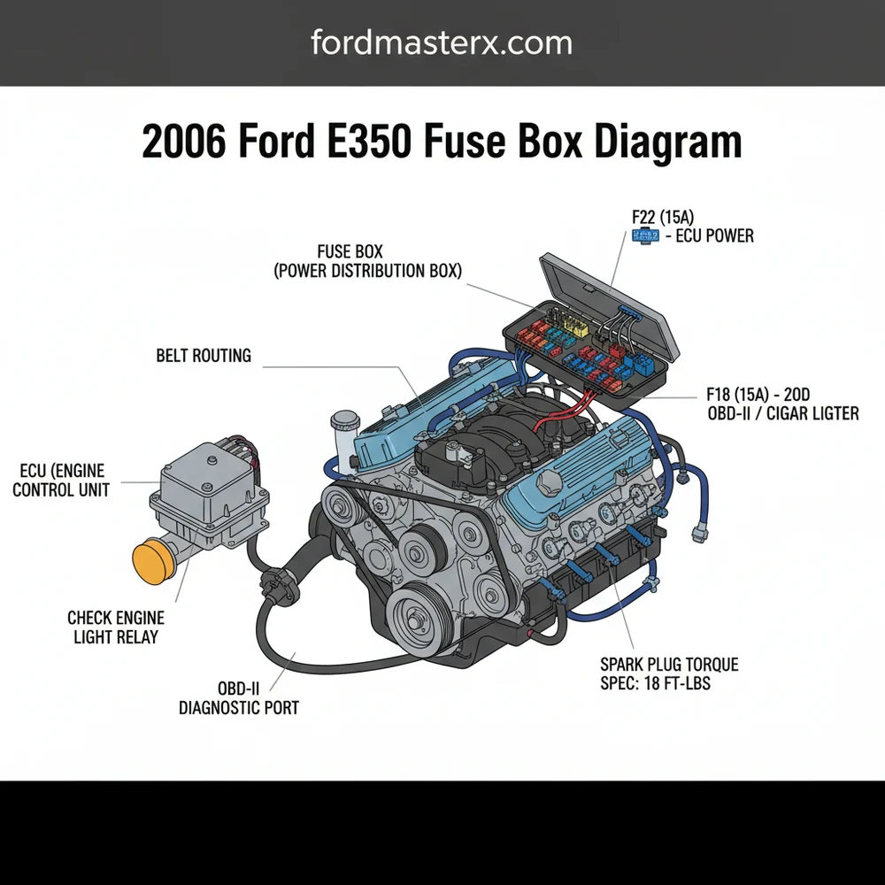
2006 Ford E350 Fuse Box Diagram: Quick Identification Guide
The 2006 Ford E350 fuse box diagram identifies the passenger compartment panel located under the dash to the left of the steering column and the power distribution box in the engine bay. It provides specific mapping for the ECU and cabin circuits, which is essential for troubleshooting a check engine light.
📌 Key Takeaways
- Primary fuse locations are under the dashboard and in the engine compartment
- The ECU and fuel system rely on specific high-amp fuses in the distribution box
- Always match replacement fuses with the exact amperage shown on the diagram
- A blown fuse can often trigger a check engine light or OBD-II connectivity issues
- Use this diagram whenever an electrical component fails to operate correctly
Troubleshooting electrical issues in a heavy-duty van like the Ford Econoline requires a logical approach and the right documentation. Whether your power outlets have stopped working, your radio is silent, or the engine won’t turn over, the most critical resource in your toolkit is a clear 2006 ford e350 fuse box diagram. Having this information at your fingertips allows you to isolate specific circuits and identify whether a simple blown fuse is the culprit or if there is a more complex underlying issue within the wiring harness. This article provides a comprehensive breakdown of the fuse locations, amperage ratings, and functional descriptions for both the interior and engine bay panels. By the end of this guide, you will understand how to locate these boxes, interpret the diagrams, and safely replace components to restore your vehicle’s electrical integrity.
The 2006 Ford E350 features a two-tier electrical protection system: the Passenger Compartment Fuse Panel and the Power Distribution Box located in the engine compartment. The interior panel, typically found beneath the instrument panel to the left of the steering column, houses lower-amperage fuses that protect cabin electronics, such as the instrument cluster, interior lighting, and the OBD-II diagnostic port. Conversely, the engine bay’s Power Distribution Box contains high-current “MAXI” fuses and relays designed for heavy-draw components. This includes the ECU (Engine Control Unit), the fuel pump, and the anti-lock brake system.
In the diagram provided below, the layout is organized into a grid format. Each slot is numbered, and the amperage is often color-coded: blue for 15A, yellow for 20A, and green for 30A. It is important to note that variations may exist depending on whether your E350 is a base cargo van, a passenger wagon, or a cutaway chassis used for ambulances or motorhomes. For instance, high-output variants may have additional relays for dual-battery setups or specialized lighting.
———————————————————–
| [01] | [02] | [03] | [04] | [05] | [06] | [07] | [08] |
| 20A | 15A | 15A | 20A | 10A | 20A | 10A | 5A |
———————————————————–
| [09] | [10] | [11] | [12] | [13] | [14] | [15] | [16] |
| 15A | 10A | 10A | 2A | 15A | 15A | 5A | 20A |
———————————————————–
| [17] | [18] | [19] | [20] | [21] | [22] | [23] | [24] |
| 10A | 15A | 10A | 15A | 15A | 20A | 20A | 20A |
———————————————————–
Note: Consult manual for specific circuit mapping (e.g., Fuse 26: OBD-II)
On the 2006 E350, Fuse 26 (20A) in the interior panel is one of the most frequently checked components. It powers the cigar lighter and the OBD-II data link connector. If your scan tool cannot communicate with the vehicle to read a diagnostic code, check this fuse first.
Reading and interpreting the fuse box diagram is a straightforward process if you follow a methodical sequence. Use the following steps to navigate your electrical system safely and effectively:
- ✓ Step 1: Access the Fuse Panels. For the interior box, remove the plastic cover panel under the dashboard near the brake pedal. For the engine bay box, look for the black rectangular plastic housing near the driver-side fender or battery. Squeeze the tabs on the sides of the cover to lift it off.
- ✓ Step 2: Orient the Diagram. Compare the physical layout of the fuses to the map printed on the inside of the fuse box cover or the diagram in this article. Look for a notch or a specific numbered corner to ensure you aren’t looking at the panel upside down.
- ✓ Step 3: Identify the Problem Circuit. If your check engine light is on and you suspect a sensor issue, look for fuses labeled for the powertrain control module or fuel injection. If the van won’t start, focus on the starter relay or fuel pump fuse in the engine compartment box.
- ✓ Step 4: Use a Multimeter or Test Light. While you can visually inspect a fuse to see if the internal metal wire is broken, a multimeter is more reliable. Set it to the continuity or ohms setting. Touch the probes to the two small metal test points on the top of the fuse. A “beep” or zero ohms indicates the fuse is good.
- ✓ Step 5: Extract the Fuse. Use the white plastic fuse puller tool often stored inside the fuse box lid. Pull the fuse straight out. Avoid using metal pliers unless the battery is disconnected, as you may cause a short circuit.
- ✓ Step 6: Verify Amperage. Never replace a blown fuse with one of a higher amperage. If the diagram calls for a 10A fuse, only use a 10A fuse. Using a higher-rated fuse can cause the wiring to overheat and potentially lead to a fire.
- ✓ Step 7: Re-Test the System. Once the new fuse is installed, turn the ignition key and check the function. If the fuse blows again immediately, you have a short circuit that needs professional investigation.
Before working on the Power Distribution Box in the engine bay, ensure the engine is off and the key is removed. High-current circuits can cause significant sparking if shorted. When tightening battery terminals or relay brackets, adhere to a torque spec of approximately 80-100 inch-pounds to ensure a solid electrical connection without stripping the threads.
When troubleshooting, many owners encounter recurring issues that appear to be electrical but may be related to mechanical strain. For instance, if you experience a frequent failure of the cooling fan relay, it might be due to restricted coolant flow or a failing water pump that is forcing the fans to run at maximum capacity for extended periods, causing the circuit to overheat. Similarly, if your check engine light is accompanied by codes for the camshaft or crankshaft sensors, do not immediately assume the sensors are dead. A blown fuse in the ECU supply line can trigger a false diagnostic code that mimics a major mechanical failure, such as a stretched timing chain or skipped timing.
Keep a spare set of fuses and a small LED flashlight in your glovebox. Electrical failures in an E350 often happen at night or while towing, and having the tools ready can save you an expensive roadside assistance bill.
Maintaining the electrical health of your 2006 Ford E350 requires more than just changing fuses. One of the best practices for high-mileage vans is to periodically inspect the underside of the Power Distribution Box for corrosion, especially if you drive in areas where road salt is common. Corrosion can increase resistance, leading to intermittent power loss that a fuse diagram won’t solve.
Additionally, be mindful of how mechanical components interact with the electrical system. A worn accessory belt can slip on the alternator pulley, resulting in low voltage. Low voltage forces electrical components to draw more current, which can prematurely blow fuses. If you find yourself replacing fuses for the blower motor or headlights frequently, check the tension and condition of your accessory belt.
When purchasing replacement parts, always opt for high-quality, name-brand fuses rather than generic bulk packs, which may not blow at the precise amperage listed. For those running heavy equipment like power inverters or tail-lifts, consider adding a dedicated auxiliary fuse block rather than tapping into existing factory circuits. This keeps the primary 2006 ford e350 fuse box diagram accurate and prevents overloading the sensitive ECU and cabin modules. By combining the data from a reliable diagram with routine maintenance, you can ensure your E350 remains dependable for years to come.
Step-by-Step Guide to Understanding the 2006 Ford E350 Fuse Box Diagram: Quick Identification Guide
Identify the electrical system that is malfunctioning to narrow down the specific fuse circuit.
Locate the appropriate fuse box using the diagram, choosing between the cabin or engine bay panels.
Understand how the fuse correlates to the ECU or the component currently failing to operate.
Apply the fuse puller tool to firmly remove the suspected blown fuse from its socket.
Verify that the replacement fuse matches the amperage and that battery terminal torque spec is maintained.
Complete the repair by using an OBD-II scanner to clear any residual diagnostic code from the system.
Frequently Asked Questions
Where is the fuse box located?
The 2006 Ford E350 features two main fuse locations. The passenger compartment fuse panel is positioned under the dashboard on the driver’s side, specifically to the left of the steering column. The secondary power distribution box is located under the hood, mounted on the driver’s side fender near the battery.
What does the diagram show?
The 2006 ford e350 fuse box diagram identifies the specific amperage rating and function for every fuse and relay. It shows which circuits control the ECU, headlights, and radio. Using the diagram prevents you from accidentally installing the wrong fuse, which could lead to electrical fires or system damage.
How many connections does the OBD-II port have?
The OBD-II port on your Ford E350 has a standard 16-pin connection. This diagnostic interface provides access to the ECU, allowing you to retrieve a specific diagnostic code. It is powered by a fuse in the central panel, so check the diagram if your scanner fails to connect to the vehicle.
What are the symptoms of a bad fuse?
Symptoms include non-functional electrical components like the horn or wipers. If the fuse for the ECU or powertrain control module fails, it may trigger a check engine light or cause a no-start condition. Always use a test light to confirm if a fuse has blown before performing complex repairs.
Can I replace this myself?
Yes, replacing a fuse in the 2006 Ford E350 is a simple DIY task. After identifying the blown fuse using the diagram, use a plastic puller to swap it for one with the same amperage. Ensure you never use a higher-rated fuse, as this can damage the vehicle’s wiring harness.
What tools do I need for this task?
You will need a basic fuse puller, often found inside the fuse box cover, and a circuit tester. To clear a check engine light after a repair, an OBD-II scanner is required. If removing battery cables, ensure you have a wrench to tighten terminals to the correct torque spec.


