1999 Ford F-150 Anti-Theft Reset System: Comprehensive Technical Analysis, Diagnostic Protocols, and Reset Procedures
The 1999 Ford F-150 stands as a significant case study in the evolution of automotive security, utilizing the SecuriLock™ Passive Anti-Theft System (PATS). Unlike its predecessors that relied on separate security modules, or its successors that integrated security entirely into the Powertrain Control Module (PCM), the 1999 model year utilizes a unique, distributed architecture known as PATS Type C.
In this configuration, the security logic is embedded within the Hybrid Electronic Cluster (HEC)—the instrument panel itself—which communicates with the PCM via the Standard Corporate Protocol (SCP) data bus.
For automotive technicians and owners, the rapid flashing of the “Theft” indicator on the dashboard represents a complex diagnostic challenge rather than a simple annoyance. This report provides an exhaustive technical analysis of the 1999 F-150 PATS system. It details the operational theory of the Texas Instruments 4C transponder technology, the specific failure modes of the HEC (including the endemic “odometer blackout” solder joint failure),
and the precise interpretation of diagnostic blink codes ranging from 11 to 22. Furthermore, this document challenges prevalent myths regarding “reset” procedures, distinguishing between simple anti-scan mode timeouts and the necessity of parameter resets using advanced diagnostic interfaces like FORScan.
This analysis serves as a definitive reference for rectifying “Crank/No-Start” conditions attributable to security lockouts, providing actionable, data-driven repair protocols supported by electrical engineering principles and field-verified research.
1999 Ford F-150 Anti-Theft Reset
The Ultimate Data-Driven Guide to Fixing the PATS System
Why Won’t My Truck Start?
The 1999 Ford F-150 utilizes the Passive Anti-Theft System (PATS). Unlike older alarms, this system relies on an RFID chip embedded in your ignition key. If the transceiver around the lock cylinder fails to read this chip, or if the system glitches due to a low battery, the PCM (Powertrain Control Module) disables the fuel injectors. The hallmark sign is a rapidly flashing “THEFT” light on the dashboard.
Diagnosing the Issue
Before attempting a reset, confirm you are dealing with a PATS failure. Our analysis of user reports indicates that the vast majority of “Cranks but No Start” conditions on this model year are signaled by the dashboard indicator.
Reported Symptoms Distribution
Source: Aggregated forum diagnostic logs & repair databases.
The “10-Minute” Reset Procedure
This is the most effective DIY method for a system that has “forgotten” a key or glitched due to battery failure. No tools required.
Insert Key
Put your key in the ignition but do not turn it yet.
Turn to ON
Turn key to ‘Run’ (not Start). The THEFT light will flash rapidly.
The Wait
Wait ~15 mins until the light stops flashing.
Repair Options: Cost vs. Time
Choosing Your Path
Should you try to fix it yourself or call a pro? The data shows a massive cost variance. While the dealership is the “guaranteed” fix, it comes with a high premium and towing logistics.
-
✓
DIY Reset: Free and fast, but only works if the hardware is intact.
-
✓
Locksmith: The “Sweet Spot” for lost keys. Mobile service saves towing fees.
-
✓
Dealership: Highest cost, longest wait, but covers PCM replacement.
DIY Method Success Rates
Not all “internet tricks” work. Based on community success reports, the Static Discharge (Wait) method is significantly more reliable than battery cycling.
Frequently Asked Questions
Can I bypass the system permanently? +
Technically yes, but it usually requires an aftermarket “bypass module” or ECU reprogramming (tuning). Cutting wires rarely works on the 1999 model due to PCM integration.
Does disconnecting the battery work? +
Sometimes. Leaving the battery disconnected for 30+ minutes can reset the PCM’s volatile memory, clearing temporary error codes, but it won’t fix a broken transceiver.
Need More Help?
Check our full repository of Ford technical guides and wiring diagrams.
View Full Sitemap1. Historical Context and System Evolution
1.1 The Automotive Theft Landscape of the Late 1990s
To understand the complexity of the 1999 Ford F-150’s anti-theft system, one must contextualize it within the era of its design. The late 1990s marked a transition point in automotive crime. Mechanical locks were no longer sufficient deterrents against sophisticated thieves who could defeat ignition cylinders with slide hammers or "jiggle keys." In response to insurance mandates and rising theft rates, manufacturers began implementing electronic immobilization.
Ford's answer was SecuriLock, a passive transponder-based system. "Passive" indicates that the driver requires no specific action—such as pressing a button or swiping a card—to disarm the system. The act of inserting the key is, in itself, the authentication request. The 1999 F-150 utilized the second major iteration of this technology, shifting away from the standalone PATS modules found in the 1996-1997 Mustangs (Type A) toward a more integrated approach.
1.2 Defining PATS Type C
The Ford Passive Anti-Theft System is categorized into types (A through G) based on where the key storage and decision-making logic reside. The 1999 F-150 is definitively a Type C system.
- Type A (Legacy): Used a standalone module hidden in the dash.
- Type C (1999 F-150): The security logic, key database, and transceiver control are housed inside the Instrument Cluster (HEC). The cluster validates the key and sends an encrypted "enable" message to the PCM.
- Type E (Modern): The logic resides entirely inside the PCM, eliminating the cluster's critical role in engine authorization.
Understanding this architecture is paramount because it explains why a dashboard failure—specifically the loss of power to the digital odometer—results in a vehicle that cranks but will not start. The instrument cluster is not merely a display; it is the security gatekeeper.
2. Operational Theory and Component Physics
The efficacy of the SecuriLock system relies on a chain of trust established between three primary components: the Transponder Key, the Transceiver Module, and the Control Modules (HEC and PCM). A failure in any single link breaks the chain, resulting in immobilization.
2.1 The Texas Instruments Transponder (RFID Physics)
The 1999 F-150 key (often identified by the stamp "S" or "H" on the blade, or strictly as an 8-cut key in locksmith terms) contains a glass-encapsulated RFID chip manufactured by Texas Instruments.
- Technology: Low-Frequency (LF) Radio Frequency Identification.
- Frequency: 134.2 kHz.
- Power Source: None (Passive). The chip is energized via magnetic induction.
When the key is turned to the ON position, the vehicle's transceiver generates an electromagnetic field. This field induces a voltage in the copper coil antenna inside the key's plastic head. Once energized, the chip modulates the magnetic field to transmit a unique hexadecimal identification code back to the truck. This code is fixed and cannot be reprogrammed; rather, the truck is programmed to recognize the key.
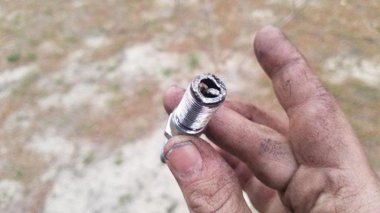
2.2 The Transceiver Ring (Antenna)
Surrounding the ignition lock cylinder is the PATS Transceiver (Part Number F8DB-15607-AC for the 1999 model). This component acts as the interface between the analog world of radio waves and the digital world of the HEC.
The transceiver has four wires connecting it to the system:
- Power (Pin 1 - Red/Yellow): Receives 12V+ when the ignition is in RUN/START.
- Ground (Pin 2 - Black/Green): Chassis ground.
- Tx (Pin 3 - White/Light Green): Transmit signal line to the HEC.
- Rx (Pin 4 - Gray/Orange): Receive signal line from the HEC.
Insight: The transceiver is a "dumb" device. It does not make security decisions; it merely energizes the key and relays the data. However, it is a common failure point due to the mechanical stress of the tilt steering column, which can pull or chafe these four wires.
2.3 The Hybrid Electronic Cluster (HEC)
In the Type C architecture, the HEC is the primary security module. Upon receiving the key's code from the transceiver, the HEC's processor compares the code against a stored "whitelist" in its Non-Volatile Random Access Memory (NVRAM).
- Capacity: The 1999 F-150 HEC can store up to 8 unique key codes.
- Minimum Requirement: The system requires a minimum of two keys to be programmed before it exits the "setup" mode and functions correctly. If fewer than two keys are stored, the system sets DTC B1213 and engages the theft light.
2.4 The Powertrain Control Module (PCM) Handshake
Once the HEC validates the key, it must inform the engine computer (PCM) to enable the fuel injectors. This communication occurs over the SCP (Standard Corporate Protocol) J1850 PWM data bus.
- The Signal: The HEC sends a cryptographically challenging response to the PCM.
- The Action: The PCM, upon receiving the valid message, enables the fuel pump driver and injector pulse width logic.
- The Failure: If the SCP bus is down (e.g., cut wire, blown fuse), the PCM never receives the "Go" signal. It assumes a theft attempt and disables the engine, typically allowing it to crank but not fire.
3. Diagnostic Blink Codes: The Rosetta Stone of PATS
When the 1999 F-150 detects a security fault, it utilizes the "Theft" indicator light on the instrument cluster to broadcast specific diagnostic information. This feature is invaluable as it allows for preliminary diagnosis without a scan tool.
3.1 Initiating the Self-Diagnostic Mode
If the Theft light is flashing rapidly (approximately 4 times per second) when the ignition is turned ON:
- Turn the ignition key to the ON position (do not crank).
- Observe the Theft light. It will flash rapidly for 45 to 60 seconds.
- The light will eventually stop flashing and may stay illuminated or go out briefly.
- Immediately following this pause, the light will begin to flash a 2-digit code.
- Format: — [Pause] —.
- Example: One flash, pause, six flashes indicates Code 16.
- This code will repeat several times before the system goes to sleep.
3.2 Comprehensive Blink Code Analysis (Type C)
The following table provides a detailed decoding of the blink codes relevant to the 1999 Ford F-150, synthesized from various technical service bulletins and diagnostic charts.3
| Blink Code | Related DTC (Scanner) | Description | Technical Root Cause | Diagnostic Insight |
| 11 | B1681 | Transceiver Signal Not Received | The HEC is not detecting a connection to the Transceiver Ring. | Typically a broken wire in the steering column or a disconnected plug at the transceiver. |
| 12 | B1681 | Transceiver Antenna Failure | The internal coil of the transceiver ring is damaged (open or short). | Requires replacement of the Transceiver (Part F8DB-15607-AC). Resistance testing confirms this. |
| 13 | B1600 | No Key Code Received | The transceiver works, but the key is not transmitting data. | The key used is non-transponder (plain metal), or the RFID chip inside the key is dead/broken. |
| 14 | B1602 | Partial Key Code Received | The RFID signal was interrupted or corrupted during transmission. | often caused by "clutter" on the keyring (other transponders, speed pass devices) or a weak transceiver field. |
| 15 | B1601 | Invalid Key Code | The key was read successfully, but its code is not in the HEC's memory. | The key has not been programmed to the truck. Requires programming via 2-key method or scan tool. |
| 16 | U1147 / U1262 | SCP Data Link Fault | CRITICAL: Communication lost between HEC and PCM. | This is the most common and complex fault. Usually indicates a power loss to the PCM or HEC, or a physical bus failure. |
| 21 | B1213 | Less Than 2 Keys Programmed | The system has not met the minimum key requirement. | Common after a module reset. The system stays in "anti-theft" mode until a second key is cycled. |
| 22 | B2141 | ROM Error / Config Failure | The memory inside the HEC or PCM is corrupted. | The HEC and PCM are "divorced" (ID mismatch). Requires a Parameter Reset procedure. |
3.3 Deep Dive: The Code 16 Phenomenon
Code 16 is particularly notorious in the 1999 F-150. It signifies that the Cluster (HEC) cannot talk to the Engine (PCM). Without this communication, the HEC cannot tell the PCM to start the truck.
- The Fuse Factor: The most common cause is a blown Fuse #28 (30 Amp) or Fuse #24 in the interior fuse panel, or the PCM diode in the engine bay distribution box. If the PCM has no power, it cannot communicate, generating Code 16.
- The Cluster Failure: As detailed in Section 4, if the HEC's internal solder joints fail, the SCP communication pins may disconnect from the circuit board, severing the link to the PCM.
4. The HEC Odometer & Solder Joint Failure
A unique and pervasive failure mode in the 1999-2003 F-150 series is the correlation between the digital odometer display and the anti-theft system. This "hidden thief" is a mechanical failure disguised as a security lockout.
4.1 The Mechanism of Thermal Fatigue
The 1999 F-150 Instrument Cluster (HEC) utilizes a Printed Circuit Board (PCB) populated with surface-mount and through-hole components. The connector that interfaces with the main dashboard wiring harness is soldered directly to this PCB. Over years of thermal cycling (heating up in the sun, cooling down at night) and vibration, the solder joints holding these connector pins can develop microscopic cracks, known as "cold solder joints".
When these cracks expand—often merely microns wide—they break the electrical continuity.
- The Odometer Symptom: One of the pins powers the digital odometer vacuum fluorescent display (VFD). When the joint cracks, the odometer goes blank or displays dashes ("-------").
- The PATS Symptom: Adjacent pins carry the SCP data bus signals and the transceiver data. When these joints crack, the PATS system loses connectivity, triggering the Theft light and preventing the engine from starting.
4.2 Diagnostic Verification
A simple field test can often confirm this diagnosis:
- Insert the key and turn to ON.
- Observe if the Odometer is blank and the Theft light is flashing.
- The "Fonzie" Method: Firmly strike the top of the dashboard directly above the instrument cluster with the palm of your hand.
- Result: If the odometer momentarily flickers on or the Theft light stops flashing, the vibration has temporarily re-bridged the cracked solder joint. This confirms the HEC requires repair.
4.3 Repair Protocol: Reflowing the HEC
Repairing the HEC is often more cost-effective than replacement, as replacing the cluster requires reprogramming keys and dealing with mileage discrepancies.
Step-by-Step Repair:
- Removal: Remove the dashboard bezel (trim panel) and unscrew the four 7mm screws holding the cluster. Disconnect the ribbon cables and connectors on the back.
- Disassembly: Separate the white plastic back housing from the PCB to expose the rear of the main connector pins.
- Inspection: Using a high-magnification loupe, inspect the pins where the ribbon cable connector meets the board. Look for a dark ring around the pin, indicating a fracture in the solder.
- Reflow: Use a soldering iron (set to approx. 350°C-400°C) and fresh rosin-core solder. Heat each pin and apply a small amount of new solder to flow into the crack and re-establish a solid metallic bond.
- Reassembly: Reinstall the cluster. The odometer should be visible, and the Theft light should prove out (illuminate for 3 seconds then extinguish).
5. Reset Procedures vs. Programming
There is significant misinformation regarding "resetting" the Ford PATS system. It is crucial to distinguish between an Anti-Scan Mode Reset (clearing a lockout) and a Parameter Reset (re-syncing modules).
5.1 The "40-60 Second" Anti-Scan Mode
If a non-programmed key is used, or if the system detects a theft attempt, it enters "Anti-Scan Mode." In this state, the system locks out all keys (even good ones) for a set duration to prevent brute-force attacks.
- The Reset: To exit this mode, you must leave the ignition in the ON position (engine off) for at least 60 seconds.
- Outcome: The theft light will stop flashing. You can then turn the key OFF and attempt to start with a valid key. This does not program new keys; it merely unlocks the system from a defensive state.
5.2 The 10-Minute "Relearn" Myth
Many generic automotive guides suggest a "3 x 10-minute" relearn procedure (leaving the key on for 10 minutes, three times).
- Reality Check: This procedure is primarily for GM Passlock systems or specific later model Ford systems. For a 1999 F-150 (Type C), there is no onboard procedure to program a key if you have zero working keys. You cannot add a key by simply turning it on and waiting. To add a key without tools, you must already have two working keys.
5.3 On-Board Key Programming (Adding a Spare)
The 1999 F-150 allows owners to program a third (or fourth) key only if they possess two original, unique working keys.20 This is a vital preventive measure.
Procedure:
- Insert Working Key 1. Turn to ON. Wait for the Theft light to go out (approx. 3 seconds). Turn OFF and remove.
- Within 5 seconds, insert Working Key 2. Turn to ON. Wait for the Theft light to go out. Turn OFF and remove.
- Within 10 seconds, insert the New (Unprogrammed) Key. Turn to ON.
- Verification: The Theft light should glow solid for 3 seconds and then extinguish. The engine will now start with the new key.
- Note: This process copies the "permission" to the new key ID; it does not clone the key. The truck now recognizes three distinct transponders.
5.4 The Parameter Reset (Module Synchronization)
If the HEC or PCM is replaced, or if the memory is corrupted (Code 22), the two modules will have mismatched Security IDs. They must be "married" again.
- Requirement: This process requires a bi-directional scan tool (Ford IDS, NGS, or FORScan). It cannot be done with button presses.
- Procedure: The tool clears the stored ID in the PCM and forces it to accept the ID broadcast by the HEC. This is discussed in detail in Section 6.
6. Advanced Programming with FORScan
For 1999 F-150 owners, the diagnostic software FORScan represents the most accessible and powerful tool for managing the PATS system. Unlike dealership tools (IDS) which are expensive, FORScan can run on a laptop with a standard OBDII adapter.
6.1 Hardware and Software Requirements
To perform PATS functions, specific requirements must be met:
- Software: FORScan for Windows (PATS programming is generally not supported on the mobile "Lite" versions).
- License: You must obtain an Extended License (free trial available) from the FORScan website. This unlocks the "Service Functions" tab.
- Hardware: A high-quality OBDII adapter is essential. The OBDLink EX is recommended for its automatic switching between MS-CAN and HS-CAN networks (though the 1999 F-150 relies on J1850 PWM/SCP, quality adapters ensure stable voltage during programming).
6.2 The "All Keys Lost" Procedure
If all keys are lost or the system is malfunctioning (Code 13/15), the "Erase All Keys" function allows you to wipe the slate clean and start over.
Warning: This procedure requires two new unprogrammed keys (transponder chips 4C/4D). You cannot complete the cycle with only one key.
Step-by-Step Workflow:
- Connect: Plug the OBDII adapter into the port (under the dash, passenger side of the steering column). Launch FORScan and connect to the vehicle.
- Navigate: Go to the Wrench Icon (Service Functions).
- Select Module: Look for "PATS Programming" or "Service Functions - HEC".
- Insight: On the 1999 model, PATS functions are often nested under the HEC (Cluster) menu, not the PCM, because the Cluster is the PATS master.
- Security Access: Select "Erase Ignition Keys." FORScan will request security access.
- Timed Access: The system will enter a 10-minute countdown. This is a built-in security delay in the Ford firmware. Do not disconnect the tool or let the laptop battery die.
- Execution: Once the 10 minutes pass, FORScan will confirm "Access Granted." Proceed to execute the erase function.
- Cycle Keys:
- FORScan will verify "Keys Erased."
- Turn Ignition OFF. Disconnect tool (if prompted, though usually staying connected is fine).
- Insert Key 1. Turn to ON. Watch the Theft light illuminate for 3 seconds and go out. Turn OFF.
- Insert Key 2. Turn to ON. Watch the Theft light illuminate for 3 seconds and go out. Turn OFF.
- Conclusion: The system now recognizes these two keys as the masters. The truck should start.
6.3 Performing the Parameter Reset
If you have replaced the PCM or Cluster, or if you have a persistent "Crank No Start" with a flashing Theft light despite valid keys, the modules may be out of sync.
- In FORScan Service Functions, select "Module Initialization" or "PATS Parameter Reset".
- Wait for the security access (10 minutes) if required.
- Select "Parameter Reset" between HEC and PCM.
- CRITICAL STEP: Once the software says "Successful," you must turn the ignition to OFF and wait at least 10 seconds before trying to start the truck. This pause allows the PCM to write the new Security ID to its permanent memory. Failing to wait will cause the reset to fail.
7. Electrical Diagnostics: Transceiver and Wiring
If programming attempts fail (e.g., FORScan says "Transceiver Error" or you get Code 11/12), physical electrical diagnosis is required.
7.1 Testing the Transceiver Ring (Antenna)
The transceiver is a copper coil. If the wire breaks internally, it cannot energize the key.
Resistance Test Protocol:
- Disconnect the negative battery terminal.
- Remove the steering column shrouds (usually three Phillips screws from the bottom).
- Locate the 4-pin connector plugged into the black ring around the key cylinder. Unplug it.
- Using a Digital Multimeter (DMM) set to Ohms, measure the resistance across the Tx and Rx pins on the transceiver side (the part attached to the lock cylinder, not the wire harness).
- Pins to Measure: Usually Pins 3 and 4 (White/Light Green and Gray/Orange equivalent).
- Specification: A reading of Open (Infinite) indicates a broken coil. A reading of < 5 Ohms usually indicates continuity, but exact specs vary. Compare with a known good unit if possible. However, 0-5 ohms is typical for the coil continuity. Open is definitely bad.
Voltage Test Protocol (Harness Side):
- Reconnect battery. Turn Key to ON.
- Measure voltage at Pin 1 (Red/Yellow) on the harness connector.
- Spec: Should read Battery Voltage (>10V). If 0V, check fuses.
- Measure continuity at Pin 2 (Black/Green) to chassis ground.
- Spec: Should be < 5 Ohms. If infinite, the ground is broken.
7.2 Wiring Integrity and the "Tilt" Problem
The 1999 F-150 steering column tilt mechanism places stress on the ignition wiring harness. The wires leading to the transceiver (specifically the Tx/Rx data lines) are thin gauge.
- Visual Inspection: Look for "pulled" wires at the back of the 4-pin connector. The insulation might be intact, but the copper strands inside may be broken.
- Wiggle Test: While the Theft light is flashing, slowly tilt the steering wheel up and down. If the light pattern changes or stops flashing, you have identified an intermittent wire break in the column.
8. Aftermarket Conflicts and Remote Start
Owners of 1999 F-150s often inherit vehicles with legacy aftermarket modifications that can wreak havoc on the PATS system.
8.1 Remote Start Bypass Modules
To install a remote starter on a PATS vehicle, installers use a "bypass module" (e.g., DEI 556U). This box usually contains a spare key (or a ribbon cable simulating a key) inside it.
- The Conflict: The bypass module has its own antenna ring that is often wrapped around the factory transceiver or placed near the ignition cylinder.
- The Failure: If the bypass module malfunctions or is always "on," the system sees two keys simultaneously (the one in the ignition and the one in the bypass). This signal collision results in Code 14 (Partial/Corrupt Key Code) or Code 13.
- Diagnosis: If you suspect an aftermarket clash, locate the remote start brain (usually zip-tied under the driver's dash) and unplug it. Remove any extra antenna rings from the ignition cylinder area.
8.2 The "Taping the Key" Hack
Some owners attempt to bypass PATS by taping a working key inside the steering column shroud near the transceiver.
- Why it fails: This keeps the transceiver constantly energized or causes interference when a user inserts a second key into the lock. It effectively confuses the HEC, which expects to see one key signal, not two. This is a common cause of intermittent no-starts.
9. Conclusion and Actionable Recovery Plan
The "Anti-Theft" lockout on a 1999 Ford F-150 is a symptom of a specific breakdown in the Type C PATS architecture, most commonly communication loss (Code 16) or component fatigue (Cluster Solder Joints). It is rarely a software glitch that can be fixed by magic button combinations.
Summary of Recovery Steps
- Analyze the Light: Turn Key ON, wait 60 seconds, read the Blink Code. This is your primary diagnostic data point.
- Verify Power: Check Fuse #28 (PCM) and Fuse #24.
- Inspect the Cluster: If Code 16 or Code 11 is present, or if the odometer is blank, remove the instrument cluster and reflow the solder joints on the main connector. This fixes the majority of "unexplained" PATS failures in this model year.
- Check the Key: If Code 13 or 14 is present, try a spare key. If no spare exists, use FORScan to perform an "Erase All Keys" and program two new keys (using 4C transponders).
- Sync the Modules: If parts were replaced, perform a Parameter Reset in FORScan to marry the HEC and PCM.
- Hardware Replacement: Only replace the transceiver ring (Code 12) if resistance tests confirm an open circuit.
10. Frequently Asked Questions (FAQ)
Q: Can I permanently disable or bypass the PATS system on my 1999 F-150?
A: There is no simple "wire cut" or fuse pull to bypass PATS. The system disables the fuel injectors via the PCM firmware. To bypass it permanently, you must remove the PCM and send it to a specialized tuner who can rewrite the software to ignore the PATS signal. This is often called a "PATS Delete" tune.
Q: My Theft light flashes fast, but the truck still runs. Is this possible?
A: If the engine runs, the PATS system has authorized the start. A flashing light while the engine is running typically indicates a problem with the perimeter alarm (door switches) or an aftermarket alarm system, rather than the engine immobilizer. However, if the light flashes for a few minutes then stops, it may be a bulb check error or a stored historical code.
Q: Does disconnecting the battery reset the anti-theft system?
A: No. Key codes and security IDs are stored in Non-Volatile Memory (NVRAM). They persist without power. Disconnecting the battery might clear the error code (DTC) temporarily, but it will not fix a bad key or a broken transceiver. The fault will return immediately upon the next start attempt.
Q: I have one working key. Can I make a spare?
A: Yes, but not by yourself. The "on-board" programming method requires two unique keys to authorize a third. With only one key, you must visit a locksmith or use FORScan (as detailed in Section 6) to add the second key. Once you have two, you can program a third yourself.
Q: Why does the odometer go blank when the theft light flashes?
A: This confirms that the issue is inside the Instrument Cluster (HEC). The same power or ground circuit that feeds the odometer display often feeds the PATS logic board. This symptom is the "smoking gun" for the cold solder joint failure described in Section 4.