Standard 7 Pin Trailer Wiring Diagram: Easy Setup Guide
A standard 7 pin trailer wiring diagram illustrates the connection between a towing vehicle and trailer. It links the ground wire, tail lights, turn signals, and electric brakes through a unified plug. Proper installation ensures signals communicate correctly, including the auxiliary hot wire for charging trailer batteries while in transit.
📌 Key Takeaways
- Provides color-coded paths for lighting, brakes, and auxiliary power.
- The ground wire is the most critical connection for circuit completion.
- Proper pin orientation is vital to prevent electrical shorts and blown fuses.
- Apply heat-shrink tubing to all connections to prevent moisture corrosion.
- Essential for installing a new plug or repairing faulty trailer signal systems.
Understanding a standard 7 pin trailer wiring diagram is essential for any towing setup, ensuring your trailer lights and electric brakes function correctly. Whether you are hauling a camper, a boat, or a heavy-duty utility trailer, having the correct diagram prevents electrical shorts and keeps you compliant with road safety regulations. This guide provides a detailed breakdown of wire colors, pin locations, and terminal connections. You will learn how to identify each circuit, understand the specific gauge requirements, and master the installation process for a reliable connection every time you hit the road.
Detailed Breakdown of the 7-Way Connector Diagram
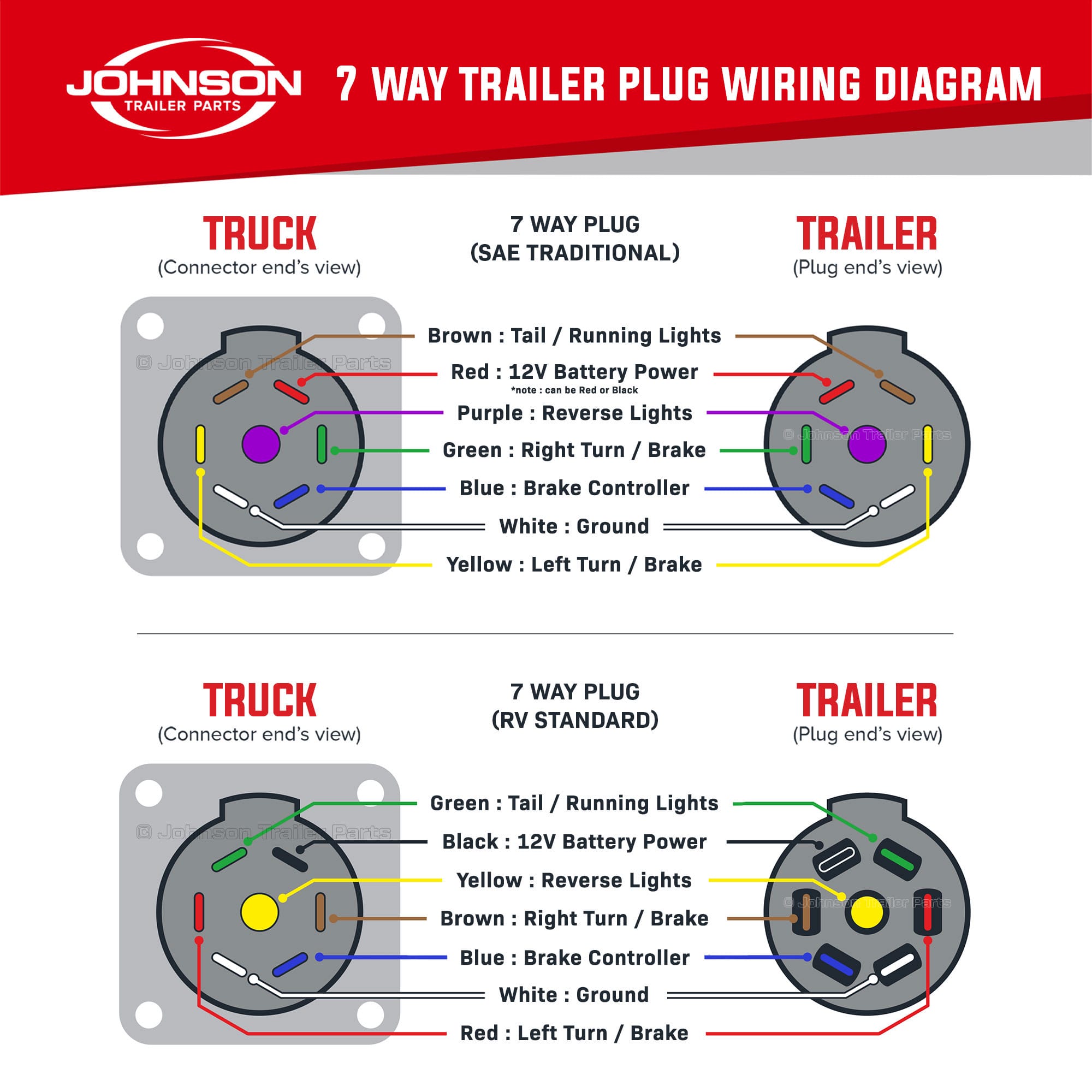
The standard 7-way connector is the gold standard for modern towing. Unlike the simpler 4-pin or 5-pin plugs, the 7-way system is designed to handle high-voltage requirements and complex signaling, including electric brakes and a dedicated battery charging line. When looking at the face of the vehicle-side socket or the back of the trailer-side plug, you will see a specific arrangement of blades or pins surrounding a center terminal.
The primary purpose of the 7-way diagram is to ensure that the tow vehicle and the trailer communicate perfectly. Each pin is assigned a specific function, color-coded for easy identification. While some manufacturers might use slight variations, the industry standard is widely accepted. The wiring usually consists of a heavy-duty ground wire, a hot wire for auxiliary power, and various signal wires that act as the traveler wire for lighting commands from the vehicle’s cockpit to the trailer’s rear.
Most 7-way plugs use the RV Standard color code. Always check your specific trailer manual, as some older utility trailers might use a different color scheme even if the pin positions remain the same.
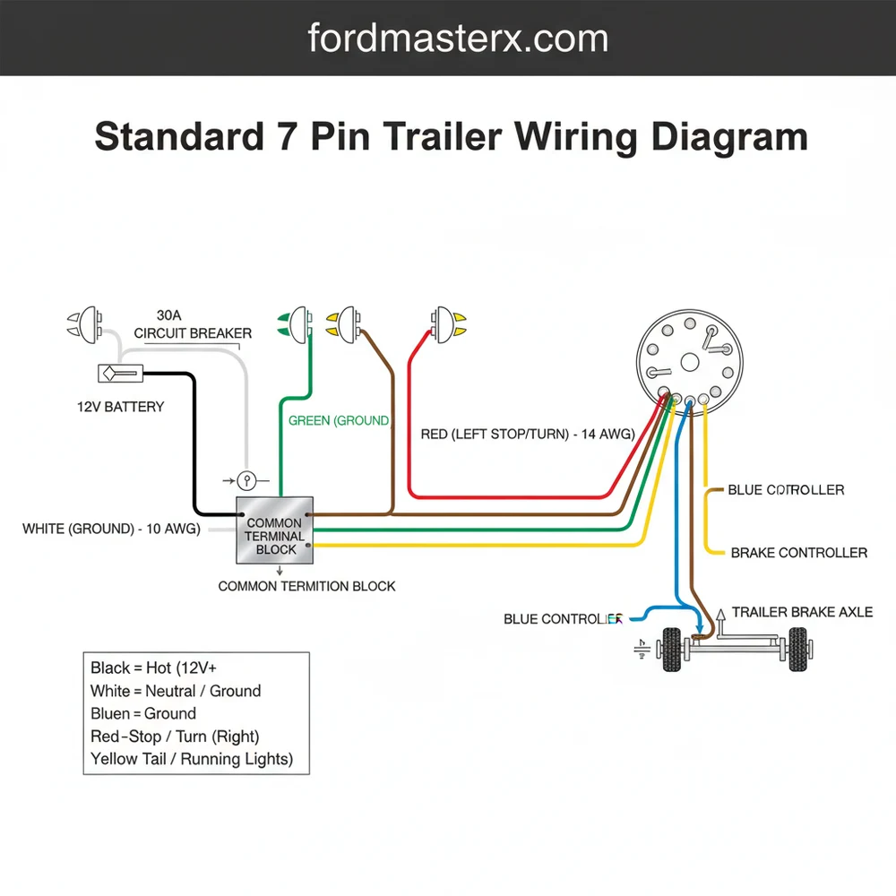
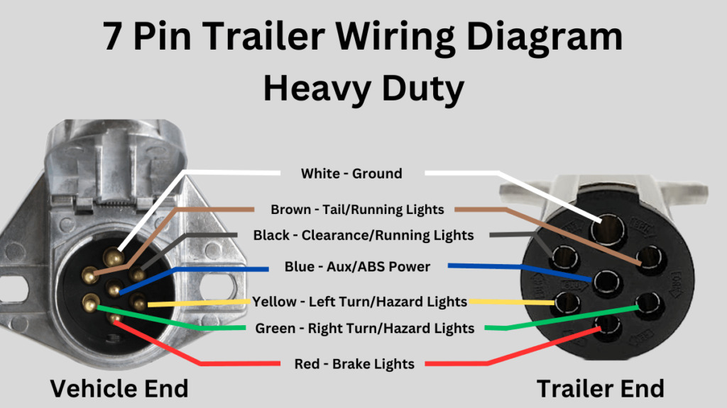
In a typical diagram, the pins are identified as follows:
- ✓ White: The ground wire, which must be connected to a common terminal to complete the electrical circuit.
- ✓ Blue: Electric brake controller output, carrying the signal to activate the trailer’s brakes.
- ✓ Green: Right turn signal and stop lamps.
- ✓ Yellow: Left turn signal and stop lamps.
- ✓ Brown: Tail lights, license plate lights, and running lights.
- ✓ Black: The 12V hot wire, used for charging the trailer battery or powering interior lights.
- ✓ Purple/Center: Reverse lights or auxiliary power for specific accessories.
[DIAGRAM_PLACEHOLDER: A circular 7-pin layout showing the pins labeled: Center (Purple-Reverse), 1 o’clock (Black-12V), 3 o’clock (Green-Right Turn), 5 o’clock (White-Ground), 7 o’clock (Blue-Brakes), 9 o’clock (Yellow-Left Turn), 11 o’clock (Brown-Tail Lights)]
Step-by-Step Guide to Installing Your 7-Way Trailer Plug
Installing or repairing a trailer plug requires precision and attention to detail. Before you begin, ensure you have the correct wire gauge for each circuit. The ground wire and the 12V hot wire typically require a thicker 10 or 12-gauge wire to handle the higher amperage, while the signal wires for turn lights can usually be 14 or 16-gauge.
Always disconnect the tow vehicle’s battery before working on the wiring. This prevents accidental shorts that could blow fuses or damage sensitive vehicle electronics.
Step 1: Prepare the Wires
Begin by stripping approximately half an inch of insulation from the end of each wire. Ensure the copper strands are clean and not corroded. If the wire looks dull or green, cut it back further until you find shiny, healthy copper. This ensures a solid connection at the brass screw terminal.
Step 2: Identify the Terminals
Open the housing of your 7-way plug. Most high-quality plugs have the terminal names (e.g., “GD” for ground, “LT” for left turn) stamped directly into the plastic or metal near each brass screw. Cross-reference these markings with your standard 7 pin trailer wiring diagram to avoid confusion.
Step 3: Connect the Ground Wire
The white ground wire is the most critical connection. In DC electrical systems, this acts as the “neutral wire” equivalent, providing the return path for the current. Insert the stripped end into the terminal marked for ground and tighten the brass screw firmly. Ensure no stray strands of wire are touching adjacent terminals.
Step 4: Connect the Hot Wire and Brakes
Next, connect the black 12V hot wire and the blue electric brake wire. Because these wires carry significant voltage and current, the connections must be incredibly secure. The hot wire provides constant power to the trailer, while the brake wire carries the modulated signal from your brake controller.
Step 5: Wiring the Signal Travelers
Now, connect the signal wires: Yellow (Left Turn/Brake), Green (Right Turn/Brake), and Brown (Tail Lights). These wires act as travelers, conveying the driver’s intentions from the vehicle to the trailer’s lighting array. Finally, connect the purple or center wire if your trailer is equipped with reverse lights or an auxiliary accessory.
Step 6: Secure the Housing and Test
Slide the plug housing back together and tighten any strain-relief clamps. Use a circuit tester or a multimeter to verify the voltage at each pin. Have a partner sit in the vehicle to operate the lights and brakes while you confirm that the correct pin is receiving power at the correct time.
Apply a small amount of dielectric grease to the terminals before closing the housing. This prevents moisture from entering the plug and causing corrosion, which is the leading cause of trailer lighting failure.
Common Issues & Troubleshooting
Even with a perfect standard 7 pin trailer wiring diagram, issues can arise over time due to road vibration and weather exposure. The most frequent problem is a “floating ground.” This occurs when the white ground wire has a poor connection to the trailer frame or the common terminal in the plug. Symptoms include dim lights, flickering, or lights that behave erratically when the brakes are applied.
Another common issue involves voltage drops. If the wire gauge used is too thin for the length of the trailer, the electric brakes may not receive enough power to stop the trailer effectively. Always ensure that the 12V hot wire and the brake wire are appropriately sized. If you notice that your vehicle’s fuses blow every time you plug in the trailer, there is likely a short circuit where a “hot” wire is touching the metal frame or a ground wire. Use your diagram to trace each circuit and look for pinched or frayed insulation. If the problem persists despite your troubleshooting, it may be time to seek professional help from an auto electrician.
Tips & Best Practices for Maintenance
To keep your trailer wiring in top condition, regular maintenance is required. Do not simply ignore the plug when the trailer is not in use. Use a protective cap to keep out dust and spiders, which love to nest in the small crevices of the 7-way socket. Periodically inspect the brass screw terminals inside the plug to ensure they haven’t vibrated loose.
- ✓ Use Heat Shrink: When splicing wires, always use adhesive-lined heat shrink tubing to create a waterproof seal.
- ✓ Check Your Gauge: Ensure your battery charge line is at least 10-gauge to handle the charging current without overheating.
- ✓ Secure the Loom: Use plastic wire loom and zip ties to secure the wiring along the trailer frame, preventing it from sagging or getting snagged on road debris.
Investing in high-quality components is another cost-saving strategy in the long run. Cheap plastic plugs tend to crack and let in moisture, whereas heavy-duty rubberized or metal plugs offer better durability. By following a standard 7 pin trailer wiring diagram and adhering to these best practices, you ensure that your towing experience is safe, legal, and hassle-free. Proper wiring is not just about convenience; it is a critical safety measure for you and everyone else on the road.
Frequently Asked Questions
Where is the common terminal located?
The common terminal or ground is usually found at the 7 o’clock or center position depending on the plug style. In a standard 7-way flat blade connector, the ground wire connects to the largest pin to ensure a solid return path for all other electrical circuits.
What does a standard 7 pin trailer wiring diagram show?
This diagram displays the specific pin assignments for right and left turn signals, tail lights, electric brakes, and auxiliary power. It serves as a visual map for connecting the traveler wire for signals and ensuring the hot wire provides a consistent charge to the trailer battery.
How many wires does a standard 7 pin trailer have?
A standard 7 pin trailer connector has seven distinct wires: ground, tail/running lights, left turn/brake, right turn/brake, electric brakes, auxiliary power, and reverse lights. Each wire is color-coded to ensure the neutral wire functions are properly isolated from power sources during installation.
What are the symptoms of a bad trailer wiring connection?
Common symptoms include flickering lights, non-functional electric brakes, or signals that operate intermittently. Often, a loose or corroded ground wire is the culprit. If the hot wire is damaged, the trailer battery won’t charge, and a faulty neutral wire connection can cause circuit cross-talk.
Can I install a 7 pin trailer plug myself?
Yes, most vehicle owners can install a 7 pin plug with basic tools and a clear diagram. You must identify each traveler wire and ensure they match the vehicle’s output. While straightforward, it requires careful attention to the common terminal connection to ensure the system is safely grounded.
What tools do I need for trailer wiring?
You will need a wire stripper, crimping tool, a multimeter or circuit tester, and electrical tape. Using heat-shrink connectors is highly recommended for weatherproofing. A standard 7 pin trailer wiring diagram is essential for identifying which color corresponds to the hot wire, ground, and signal functions.