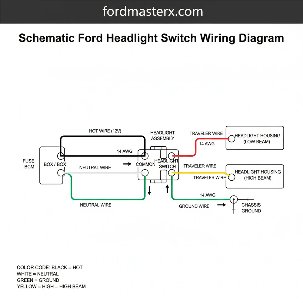
Schematic Ford Headlight Switch Wiring Diagram: Easy Guide
A schematic ford headlight switch wiring diagram illustrates how power flows from the battery hot wire to the switch terminals. It identifies the ground wire, common terminal, and specific outputs for high/low beams and parking lights. Understanding this layout is essential for diagnosing dim lights or intermittent switch failure in Ford vehicles.
📌 Key Takeaways
- Visualize the flow of electricity between the battery and lighting fixtures
- Identify the common terminal for consistent power distribution
- Ensure a solid ground wire connection to prevent flickering
- Use the diagram to map out aftermarket lighting upgrades or repairs
- Essential for diagnosing when headlights or dash lights fail to activate
When tackling an automotive electrical project, having access to an accurate schematic ford headlight switch wiring diagram is the difference between a successful repair and a blown fuse. Ford vehicles, ranging from classic trucks to modern SUVs, utilize a specific logic for their lighting systems that often integrates the headlights, parking lights, and interior instrument clusters into a single control point. This guide is designed to help DIY enthusiasts and professional mechanics decode the complex web of wires, identify terminal functions, and understand the flow of electricity from the battery to the lamps. By the end of this article, you will have a thorough understanding of pinout configurations, wire color codes, and the necessary steps to troubleshoot or replace a faulty headlight switch with confidence.
Most Ford headlight switches function as a “master controller” for the exterior lighting. Unlike a simple residential light switch that might use a brass screw for a traveler wire, an automotive switch manages multiple independent circuits—including high-current headlight loads and low-current dimming circuits for the dashboard—simultaneously.
Understanding the Ford Headlight Switch Schematic
The schematic for a Ford headlight switch typically represents a multi-position pull or rotary switch. In classic models, this is often a heavy-duty pull-knob switch located on the dash, while newer models feature a rotary dial on the left side of the steering column. Regardless of the physical form, the electrical schematic remains fairly consistent in its logic. The switch acts as a gatekeeper for the hot wire coming directly from the battery or the fuse box. This primary power source is usually a thick gauge wire, often 10 or 12 AWG, to handle the significant voltage and amperage required by halogen or LED headlamps.
Within the diagram, you will notice several specific terminal labels. The most common are ‘B’ for Battery (the common terminal for input power), ‘H’ for Headlights, ‘R’ for Rear/Parking lights, and ‘I’ for Instrument panel lights. The ground wire in these systems is often overlooked because the switch body itself was historically grounded to the metal dashboard. However, in modern plastic-interior vehicles, a dedicated ground wire is essential for the internal illumination of the switch.
A key distinction in Ford’s wiring logic is the use of an internal thermal circuit breaker. Unlike a standard fuse that simply blows and stops all current, the internal breaker in a Ford switch may “trip” and reset once it cools down. This is a safety feature designed to prevent a total blackout while driving if a short occurs. When looking at the diagram, this is represented as a zigzag line within the switch housing. Furthermore, the diagram will show the path to the dimmer switch. In many Ford configurations, the headlight switch sends power to a secondary “dimmer” (either a floor-mounted foot switch or a steering column stalk) which then acts as a traveler wire router to select between high and low beams.
[DIAGRAM_PLACEHOLDER: A detailed wiring schematic showing a 12V battery source (Hot Wire) entering a Ford headlight switch at Terminal B. The diagram shows output lines: Terminal H (Blue/Red) going to the Dimmer Switch, Terminal R (Brown) going to Parking/Tail Lights, and Terminal I (Light Blue/Red) going to the Instrument Cluster. A Ground Wire is shown connected to the switch housing or a dedicated Pin G.]
Step-by-Step Guide to Reading and Implementing the Wiring

Navigating a schematic ford headlight switch wiring diagram requires a systematic approach to ensure safety and functionality. Follow these steps to interpret the diagram and perform your installation or repair.
- ✓ Step 1: Identify the Main Power Feed. Locate the “Hot Wire” on your schematic. In most Ford trucks, this is a solid Black/Orange or Red wire. This is your common terminal that provides constant 12V power regardless of the ignition position.
- ✓ Step 2: Map the Parking Light Circuit. Find the terminal marked ‘R’. This wire (often Brown) distributes power to the front parking lamps, rear tail lights, and side markers when the switch is in the first or second position.
- ✓ Step 3: Connect the Headlight Output. The ‘H’ terminal is the primary output for the main lamps. On the schematic, follow this wire to the dimmer switch. It is usually a larger gauge wire to prevent overheating.
- ✓ Step 4: Establish the Grounding Path. While DC systems don’t use a neutral wire like AC house wiring, the ground wire serves the same purpose of completing the circuit. Ensure the switch has a clean connection to the vehicle chassis to prevent flickering.
- ✓ Step 5: Test the Instrument Dimmer. The schematic will show a variable resistor (rheostat) inside the switch. This controls the voltage sent to the dash lights via the ‘I’ terminal. Rotate the knob on the physical switch to ensure the path on the diagram matches the physical output.
Tools and Materials Needed
To work with these diagrams effectively, you will need a digital multimeter to verify voltage, wire strippers, high-quality electrical tape or heat-shrink tubing, and a set of terminal crimpers. Unlike residential wiring where you might look for a brass screw to secure a wire, automotive connections use spade terminals or specialized plastic pigtail connectors.
Always disconnect the negative battery cable before working on the headlight switch. The “Hot Wire” going to the switch is typically unfused or connected to a high-amperage fusible link; an accidental short to the metal dashboard can cause an immediate fire.
Common Issues and Troubleshooting Techniques

One of the most frequent problems users encounter is the “cycling” of headlights. This happens when the internal circuit breaker in the Ford switch trips due to excessive heat. By consulting the schematic ford headlight switch wiring diagram, you can determine if the overload is caused by a short in the “H” circuit or if you have installed high-wattage bulbs that exceed the switch’s design capacity.
Another common issue involves the dimming of the dashboard lights. If the interior lights don’t work but the headlights do, the schematic helps you isolate the ‘I’ terminal and the rheostat. You can use a multimeter to check for voltage at the ‘I’ pin; if you have input at ‘B’ but nothing at ‘I’ when the knob is turned, the internal ceramic resistor in the switch is likely cracked or burnt.
If you find that your parking lights work but the headlights do not, the diagram points you toward the traveler wire leading to the dimmer switch. Since the power for both circuits enters through the same common terminal, a failure in only one system usually indicates a problem downstream from the main headlight switch or a failure of the specific internal contact for that circuit.
Tips and Best Practices for Ford Wiring
When working with an older schematic ford headlight switch wiring diagram, it is a “pro move” to install a relay kit. The original Ford design routes all the headlight current directly through the switch. Over time, this causes the contacts to degrade and the voltage to drop, resulting in dim headlights. By using the switch only as a “trigger” for a relay, you move the high-current load away from the dash and directly to the battery using a heavy gauge wire.
When replacing the switch, apply a small amount of dielectric grease to the terminals. This prevents oxidation and ensures a low-resistance connection, which is vital for maintaining consistent voltage to your lighting system.
Always verify your wire colors against the specific year and model of your vehicle. While Ford generally stuck to a standard (e.g., Brown for parking lights), mid-generation changes can occur. Use the schematic as a map, but use your multimeter as your eyes to confirm that the “Hot Wire” is indeed hot before making permanent connections.
Finally, ensure that all ground wire connections are made to bare metal. Any paint or rust on the chassis will act as an insulator, leading to high resistance. In automotive electronics, resistance creates heat, and heat is the primary enemy of the headlight switch. By following the schematic ford headlight switch wiring diagram and adhering to these best practices, you ensure a safe, bright, and reliable lighting system for your vehicle.
Whether you are performing a simple replacement or a full-scale electrical restoration, understanding the relationship between the common terminal, the output leads, and the various circuit loads is essential. With the right diagram and a methodical approach, you can master the complexities of Ford automotive wiring and keep your path illuminated for years to come.
Frequently Asked Questions
Where is the Ford headlight switch located?
The headlight switch is typically located on the left side of the dashboard, either as a pull-knob or a rotary dial. In some Ford truck models, it is positioned just below the vent or integrated into the multi-function lever on the steering column for easier driver access.
What does a Ford headlight switch diagram show?
The diagram provides a visual map of the internal switch logic, showing how power enters through the hot wire and exits to various lighting circuits. It labels color-coded wires, pin numbers, and terminal functions like the rheostat for dimming dashboard lights and the dome light override.
How many wires does a Ford headlight switch have?
Most Ford headlight switches utilize between seven and ten wires depending on the vehicle year and trim level. These typically include the main power feed, ground wire, parking lamp output, headlight output, instrument panel illumination, and a dedicated circuit for the interior dome light activation.
What are the symptoms of a bad Ford headlight switch?
Common symptoms include headlights that won’t turn on, flickering lights, or dashboard illumination that stays dark. You might also notice a burning smell from the dash or the switch feeling hot to the touch, indicating internal resistance or a short circuit within the switch’s common terminal.
Can I replace a Ford headlight switch myself?
Yes, replacing a Ford headlight switch is a common DIY task. Most switches are held in by spring clips or a single retaining nut. By following a wiring diagram and disconnecting the battery first, you can safely swap the unit and reconnect the harness in under 30 minutes.
What tools do I need for Ford headlight switch wiring?
To work with the switch wiring, you will need a flat-head screwdriver or trim removal tool to pop off the dash bezel. A digital multimeter is essential for testing for 12V at the hot wire and checking the ground wire for continuity during the troubleshooting process.


