OBD2 Data Link Connector Wiring Diagram: Easy Setup Guide
An OBD2 data link connector wiring diagram identifies the 16-pin layout used for vehicle diagnostics. Pin 16 acts as the battery hot wire, while pins 4 and 5 serve as the ground wire connections. This standard configuration allows scanners to communicate with the vehicle’s computer via the data pins.
📌 Key Takeaways
- Identifies power, ground, and communication pins for diagnostics.
- Pin 16 is the most critical for powering scan tools.
- Ensure the ignition is off before testing terminal continuity.
- Use a multimeter to check for 12V power on pin 16.
- Use this diagram when a scan tool fails to communicate.
Finding an accurate obd2 data link connector wiring diagram is a critical first step for any vehicle owner or technician looking to diagnose communication errors, check engine lights, or electrical faults. The On-Board Diagnostics II (OBD2) system serves as the universal interface between your vehicle’s computer networks and diagnostic tools. Without a clear understanding of the 16-pin layout, you risk misidentifying critical communication lines or, worse, causing a short circuit in the Electronic Control Unit (ECU). This guide provides a detailed breakdown of the standardized pin assignments, wire color conventions, and testing procedures. By the end of this article, you will be able to confidently identify power, ground, and data signals to ensure your diagnostic port is functioning at peak performance.
The Data Link Connector (DLC) is always a 16-pin trapezoidal connector. While the layout is standardized by SAE J1962, the specific wire colors can vary significantly between manufacturers like Ford, GM, Toyota, and BMW. Always verify your specific vehicle service manual alongside this general diagram.
Understanding the OBD2 Data Link Connector Wiring Diagram Layout
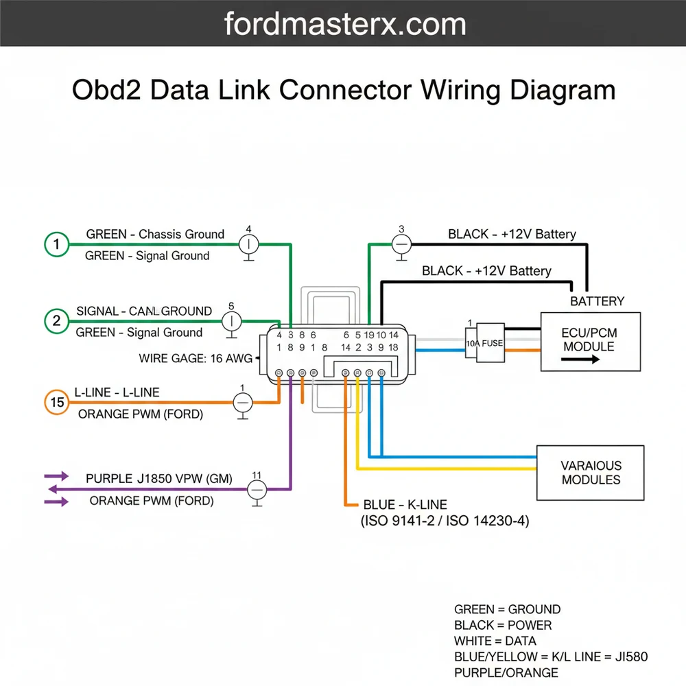
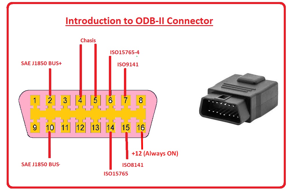
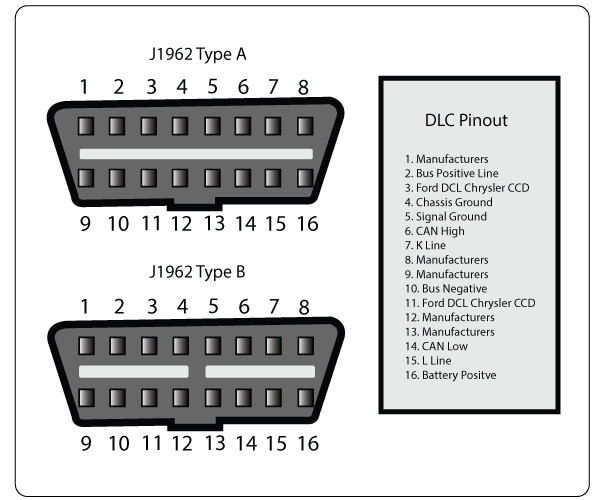
The obd2 data link connector wiring diagram represents a 16-pin female plug, usually located within two feet of the steering wheel. The pins are arranged in two rows of eight. When looking directly at the face of the connector, the wider side is at the top, and pins are numbered 1 through 8 from left to right. The bottom row contains pins 9 through 16, also ordered left to right.
In this wiring architecture, the hot wire is consistently located at Pin 16. This pin provides unswitched battery voltage (B+) directly from a fused circuit to power the scan tool. Unlike residential wiring where a brass screw might secure a hot wire to a terminal, the OBD2 port uses small, crimped metal terminals that must maintain high tension to ensure a stable data connection.
The grounding system in an OBD2 diagram is split into two distinct paths to prevent electrical noise from interfering with data. Pin 4 is the chassis ground wire, which connects directly to the vehicle’s metal frame. Pin 5 acts as the signal ground or common terminal for the electronic modules. This separation ensures that high-current spikes on the chassis ground do not distort the sensitive low-voltage data signals traveling across the bus.
Data transmission is handled by several protocols, but the most common in modern vehicles is the Controller Area Network (CAN). This involves a “twisted pair” of wires: CAN High (Pin 6) and CAN Low (Pin 14). These function similarly to a traveler wire in a multi-way switch circuit, moving signals back and forth between different “stations” or control modules in the vehicle. The integrity of these wires is paramount; even a slight change in the gauge or length of these wires can alter the resistance and crash the entire data bus.
[DIAGRAM_PLACEHOLDER: A 16-pin trapezoidal OBD2 connector diagram. Top row: Pin 1 (Manufacturer specific), Pin 2 (Bus +), Pin 3 (Manufacturer specific), Pin 4 (Chassis Ground), Pin 5 (Signal Ground), Pin 6 (CAN High), Pin 7 (K-Line), Pin 8 (Manufacturer specific). Bottom row: Pin 9 (Manufacturer specific), Pin 10 (Bus -), Pin 11-13 (Manufacturer specific), Pin 14 (CAN Low), Pin 15 (L-Line), Pin 16 (12V Battery Power).]
Step-by-Step Guide to Reading and Testing the Wiring Diagram
To effectively use an obd2 data link connector wiring diagram for repairs or installation, you must follow a methodical approach. Testing the port is often necessary when a scan tool fails to communicate with the vehicle (a “No Link” error).
- ✓ Step 1: Visual Inspection. Begin by inspecting the physical housing of the DLC. Look for pushed-back pins or corrosion. Because these connectors are often near the driver’s feet, they can accumulate dust or be kicked, causing the pins to lose their grip.
- ✓ Step 2: Identify Power (Pin 16). Set your digital multimeter to DC voltage. Place the red probe on Pin 16 and the black probe on a known good chassis ground. You should see approximately 12.6V (battery voltage). This is your hot wire. If there is no voltage, check the fuse—often shared with the cigarette lighter or auxiliary power outlet.
- ✓ Step 3: Verify the Grounds (Pins 4 & 5). Switch your meter to the Ohms (resistance) setting. Test the resistance between Pin 4 and the vehicle frame, then Pin 5 and the frame. Both should show less than 0.1 ohms. Pin 5 is the common terminal for data; high resistance here will cause erratic scan tool behavior.
- ✓ Step 4: Check CAN Bus Resistance (Pins 6 & 14). With the vehicle battery disconnected, measure the resistance across Pin 6 and Pin 14. A healthy CAN bus should read approximately 60 ohms. This is because the system uses two 120-ohm terminating resistors in parallel. If you see 120 ohms, one resistor or the traveler wire path to it is broken.
- ✓ Step 5: Trace Manufacturer-Specific Pins. Pins 1, 3, 8, 9, 11, 12, and 13 are often used for proprietary systems like airbags or ABS. Refer to your specific vehicle’s obd2 data link connector wiring diagram to see if these carry a neutral wire equivalent or a secondary communication signal.
When testing pins, never shove your multimeter probes directly into the female terminals. This can stretch the metal, leading to poor contact later. Use a “breakout box” or thin back-probe pins to maintain the integrity of the connector.
The gauge of wire used for OBD2 circuits is typically 18 to 22 AWG. If you are repairing a broken wire, ensure you use the same thickness. Using a wire that is too thin can increase resistance, while a wire that is too thick may be difficult to crimp into the tiny terminal pins.
Do not bridge Pin 16 to any other pin with a jumper wire. Pin 16 carries full battery amperage; shorting it to a data line (like Pin 6 or 14) can instantly fry the vehicle’s engine control module or other expensive processors.
Common Issues & Troubleshooting
The most frequent issue encountered with the obd2 data link connector wiring diagram is a lack of power at Pin 16. In many vehicles, this circuit is not labeled “OBD2” in the fuse box. Instead, it is frequently shared with the “CIG” or “AUX” circuit. If your phone charger doesn’t work in the car, your scan tool likely won’t either.
Another common problem is “Communication Error” messages. This is often caused by a “floating ground” where the common terminal (Pin 5) has developed high resistance due to corrosion at the main engine ground strap. Using your wiring diagram to locate the physical ground point on the engine block or inner fender is the best way to resolve this.
If you find that the scan tool powers up but cannot see the ECU, the traveler wire pair (CAN High/Low) might be shorted to each other or to ground. Look for aftermarket accessories like alarms or remote starters that may have been spliced into these sensitive data lines incorrectly.
Tips & Best Practices for Wiring Maintenance
When working with an obd2 data link connector wiring diagram, precision is your best friend. If you are installing an aftermarket display or a telematics device, try to use a “pass-through” harness rather than cutting and soldering the factory wires. This preserves the original gauge and shielding of the factory harness.
- ✓ Maintain Pin Tension: If a pin feels loose, you can sometimes use a dental pick to gently tension the internal metal tab, but replacement is usually safer.
- ✓ Use Dielectric Grease: A tiny amount of dielectric grease can prevent oxidation, especially in humid climates, without affecting the voltage transmission across the data pins.
- ✓ Label Repairs: If you must replace a ground wire or power lead, label it clearly behind the dashboard for future troubleshooting.
Quality components are essential. If you are building a custom harness, look for high-temperature cross-linked polyethylene (TXL) wire. This is standard in automotive applications and is much more durable than the standard PVC-insulated wire found in home hardware stores. While you won’t find a brass screw here, high-quality gold-plated pins can provide superior data transfer for high-speed CAN networks.
In conclusion, mastering the obd2 data link connector wiring diagram allows you to bridge the gap between mechanical hardware and digital diagnostics. By identifying the hot wire at Pin 16, ensuring the common terminal and ground wire are solid, and protecting the CAN traveler wire pair, you ensure that your vehicle remains “talkative” with diagnostic equipment. Whether you are a DIYer or a professional, a methodical approach to these 16 pins will save time, money, and frustration during your next repair.
Frequently Asked Questions
Where is the OBD2 data link connector located?
The connector is usually found under the dashboard on the driver’s side, within three feet of the steering wheel. It is often exposed or behind a small plastic panel. In some vehicles, it may be near the center console or behind the ashtray, though this is less common.
What does an OBD2 wiring diagram show?
It illustrates the specific pin assignments for the 16-pin DLC port. It details which pins handle the battery constant hot wire, the signal and chassis ground wire, and the various CAN bus or K-Line data communication protocols used by the vehicle’s electronic control units for diagnostics and programming.
How many connections does the OBD2 connector have?
The connector features 16 standard pins arranged in two rows. While all 16 slots are present, not all are always wired depending on the protocol. Most vehicles use pin 16 for power, pins 4 and 5 for ground, and pins 6 and 14 for high-speed CAN bus communication.
What are the symptoms of a bad data link connector?
Common signs include a scan tool failing to power up when plugged in or receiving a ‘No Communication’ error message. This usually indicates a blown fuse on the hot wire circuit, a loose ground wire, or bent pins within the common terminal housing itself that prevent a solid connection.
Can I repair the OBD2 wiring myself?
Yes, if you have basic electrical knowledge and a wiring diagram. You can often depin the connector to replace damaged wires or resolder a loose ground wire. However, avoid messing with data lines unless you are certain of the protocol, as this can disrupt the entire vehicle communication network.
What tools do I need for OBD2 wiring repair?
You will need a digital multimeter to test for voltage and continuity across the pins. A pin extraction tool is useful for removing terminals without damage, while a soldering iron or high-quality crimpers are necessary for securing new connections to the hot wire or the common terminal ground.