MSD 2 Wire Distributor Wiring Diagram: Easy Setup Guide
The MSD 2 wire distributor wiring diagram shows how to connect the magnetic pickup to the ignition control box. The violet wire connects to the positive terminal while the green wire attaches to the negative. Always ensure a clean ground wire connection and verify the hot wire provides switched 12V power for ignition.
📌 Key Takeaways
- Primary purpose is to sync the distributor pickup with the ignition box
- The violet and green twisted pair are the most critical wires to identify
- Never run signal wires near spark plug wires to avoid interference
- Use a dedicated ground wire for the ignition box to prevent misfires
- Use this diagram when installing a Pro-Billet or magnetic pickup distributor
Implementing a high-performance ignition system is a significant milestone for any engine build, and the msd 2 wire distributor wiring diagram is the critical roadmap required to make it happen. Whether you are replacing a points-style distributor or upgrading to a more reliable magnetic pickup system, understanding the nuances of these two specific wires is the difference between a crisp-firing engine and one that refuses to start. This guide is designed to demystify the connection process, providing you with a clear visual and technical understanding of how the distributor interacts with your ignition control box. By the end of this article, you will know exactly how to identify your wires, establish a clean circuit, and ensure your engine benefits from the precise timing that a magnetic pickup distributor provides.
The heart of the msd 2 wire distributor wiring diagram lies in the two-wire magnetic pickup assembly located inside the distributor housing. Unlike a traditional distributor that uses mechanical points to break a circuit, this system utilizes a reluctor wheel and a magnetic sensor. As the reluctor wheel spins, it creates a small AC voltage signal that is sent to the ignition control box. This signal tells the box exactly when to fire the coil. The two wires responsible for this are almost universally color-coded as Violet and Green.
In a standard installation, the Violet wire represents the positive (+) signal, and the Green wire represents the negative (-) signal. These two wires are typically twisted together from the factory. This twisting is not merely for aesthetics; it serves a vital functional purpose. Because the signal generated by the distributor is a low-voltage pulse, it is highly susceptible to electromagnetic interference (EMI) from the alternator or spark plug wires. The twisted pair acts as a shield, ensuring the signal remains “clean” as it travels toward the ignition module. In the diagram, these wires terminate in a dedicated two-pin plastic connector, which is designed to plug directly into the matching harness of an MSD 6-series, 7-series, or 8-series ignition box.
Beyond the signal wires, the broader wiring environment includes the power and ground circuits that support the ignition box. While the distributor itself only has two signal wires, the system cannot function without a dedicated hot wire providing 12V voltage to the ignition control unit. Additionally, the system requires a robust ground wire to complete the circuit. In many high-performance setups, the distributor body itself acts as a common terminal for the internal magnetic sensor, meaning the physical installation of the distributor into the engine block must be clean and free of excessive paint or debris to ensure proper grounding through the engine.
The MSD 2-wire distributor does not connect directly to the ignition coil. It must be connected to an ignition control box (like an MSD 6AL), which then controls the coil. Connecting the distributor directly to the coil will result in a lack of spark and potential damage to the magnetic pickup.
[DIAGRAM_PLACEHOLDER: A detailed wiring schematic showing an MSD 2-wire distributor with Violet and Green wires twisted, connecting to a 2-pin connector on an MSD 6AL Ignition Box. The box shows a Heavy Red wire to the Battery Positive, a Heavy Black wire to the Battery Negative, a Small Red wire to the Ignition Switch, and Orange/Black wires to the Ignition Coil.]
Properly interpreting and implementing the msd 2 wire distributor wiring diagram requires a systematic approach. Follow these steps to ensure a professional-grade installation.
Step 1: Inspect the Distributor and Harness
Before mounting the distributor, examine the two-wire harness exiting the base. You should see a Violet wire and a Green wire. Ensure the insulation is intact and the two-pin connector is free of corrosion. If you are using an older distributor, you may need to clean the terminals to ensure a solid connection.
Step 2: Prepare the Ignition Box Connections
The ignition box is the “brain” of the operation. Locate the magnetic pickup input on the box. This is usually a short harness with a matching two-pin connector. Do not confuse this with the white wire used for points-style triggers; the white wire is NOT used when connecting a 2-wire magnetic distributor.
Step 3: Route the Signal Wires
Route the Violet and Green wires from the distributor to the ignition box. It is crucial to keep these wires away from “noisy” electrical components. Avoid running them parallel to the spark plug wires or the alternator charging lead. If you must cross a high-current wire, do so at a 90-degree angle to minimize interference. Think of these as the traveler wire pair that carries the vital timing data; any interference here will cause erratic timing or “engine kickback.”
Step 4: Establish Power and Ground
Connect the heavy-duty 10-12 gauge Red wire from the ignition box directly to the battery positive terminal. Connect the heavy Black ground wire directly to the battery negative terminal or a high-quality engine ground. For the ground connection, using a brass screw or a dedicated grounding stud on the frame is recommended to prevent oxidation over time.
Step 5: Connect the Switched 12V Source
The small Red wire on the ignition box is the hot wire that turns the system on. This should be connected to a source that has 12V voltage only when the ignition key is in the “On” and “Start” positions. In some older vehicles, this may be the wire that originally went to the positive side of the coil.
Step 6: Plug in the Magnetic Pickup
Snap the two-pin connector from the distributor into the magnetic pickup connector on the ignition box. The connectors are keyed, so they should only fit one way. However, always double-check that Violet meets Violet and Green meets Green.
Step 7: Final Coil Connections
The Orange wire from the ignition box goes to the coil positive (+) terminal, and the Black wire goes to the coil negative (-) terminal. Note that in this configuration, the coil negative acts as a signal return, similar to a neutral wire in an AC circuit, though it is technically the switched ground controlled by the box.
Never use a “test light” to check for signals on the Violet or Green wires. The sensitive magnetic pickup can be damaged by the current draw of a traditional test light. Use only a high-impedance digital multimeter if testing is required.
Even with a perfect msd 2 wire distributor wiring diagram, issues can arise during the first start-up. The most common problem is reversed polarity. If the Violet and Green wires are swapped, the ignition timing will be retarded by several degrees, and the engine will likely struggle to start or “pop” through the carburetor.
If you experience no spark at all, the first thing to check is the voltage at the small Red wire. If the box isn’t receiving a full 12V while cranking, the magnetic pickup won’t trigger the system. Another frequent culprit is a poor ground. If the heavy Black ground wire is connected to a painted surface or a loose brass screw, the circuit will lack the current necessary to fire the coil.
Intermittent misfires at high RPM are often caused by EMI. If the Violet and Green signal wires are not sufficiently twisted or are run too close to the spark plug wires, the box may receive “ghost” signals, causing it to fire the coil at the wrong time. If troubleshooting these basics doesn’t solve the issue, it may be time to test the resistance of the magnetic pickup itself using a multimeter; it should typically read between 400 and 1,300 ohms.
For the cleanest possible installation, use a shielded wire sleeve over the Violet and Green wires. Connect the shield’s drain wire to the engine ground at one end only to create a “Faraday cage” effect that blocks virtually all outside electrical noise.
To ensure the longevity and reliability of your ignition system, follow these best practices:
- ✓ Dielectric Grease: Apply a small amount of dielectric grease to the two-pin connector terminals to prevent moisture intrusion and corrosion.
- ✓ Wire Gauge Integrity: Never downsize the power or ground wires. The 10-12 gauge wires provided with the box are designed to handle high current surges.
- ✓ Heat Protection: Use high-temperature wire loom for any section of the harness passing near the exhaust headers or intake manifold.
- ✓ Avoid Crimping Alone: For the best connection, crimp your terminals and then follow up with a small amount of solder to ensure the connection never vibrates loose.
- ✓ Check Air Gap: Periodically check the air gap between the reluctor wheel and the magnetic pickup inside the distributor. A gap that is too wide will result in a weak signal.
Maintaining your ignition system is relatively simple once the initial wiring is correct. Every few months, check the tightness of your common terminal and ground points. Vibration from the engine can loosen even the most secure brass screw over time. By adhering to the msd 2 wire distributor wiring diagram and following these installation steps, you ensure that your vehicle remains reliable, efficient, and ready to perform whenever you turn the key. Proper wiring is not just about making a connection; it is about creating a stable environment for your engine’s most critical electrical signals.
Step-by-Step Guide to Understanding the Msd 2 Wire Distributor Wiring Diagram: Easy Setup Guide
Identify the violet and green signal wires emerging from the distributor base.
Locate the matching two-pin connector on your MSD ignition control box.
Understand how the traveler wire signal moves from the distributor to the common terminal.
Connect the hot wire to a 12V switched power source that remains live during cranking.
Verify that the ground wire is attached to a clean, unpainted surface on the chassis.
Complete the installation by checking for a consistent spark using a timing light.
Frequently Asked Questions
Where is the magnetic pickup located?
The magnetic pickup is located inside the MSD distributor housing, directly beneath the rotor. It consists of a stationary coil and a reluctor wheel attached to the distributor shaft. This component generates the voltage signal required to trigger the ignition box at the precise moment for engine combustion.
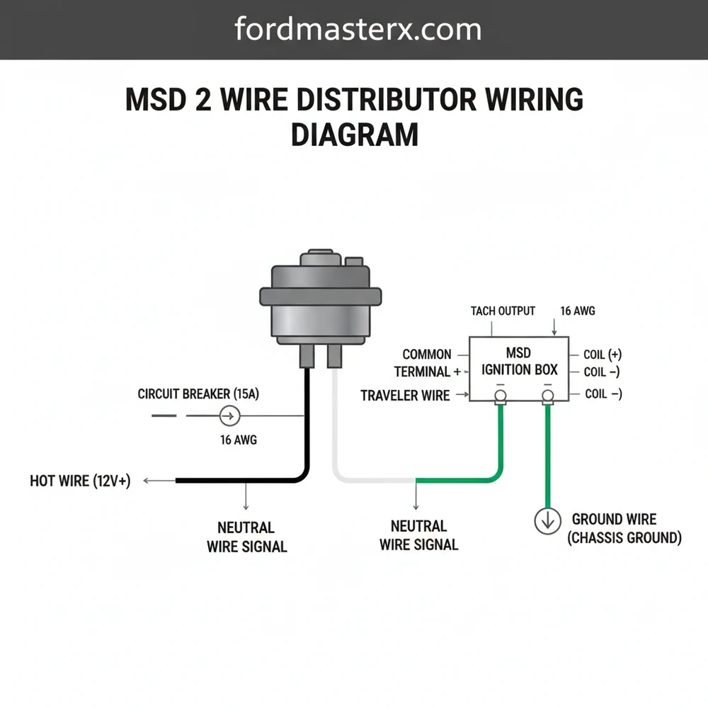
What does this wiring diagram show?
The MSD 2 wire distributor wiring diagram shows the specific routing for the two-pin connector wires. It details how the signal travels from the distributor to the ignition control unit, ensuring the polarity is correct so the ignition timing remains stable across the entire RPM range of the engine.
How many wires does the MSD distributor have?
A standard MSD magnetic pickup distributor has two main signal wires, typically violet and green. While a residential circuit might have a neutral wire, this automotive DC system relies on these two wires to complete the trigger circuit between the distributor’s internal pickup and the ignition control module.
What are the symptoms of a bad distributor pickup?
Symptoms of a failing pickup include sudden engine stalling, a no-start condition, or erratic ignition timing. If the internal wires are frayed or the magnetic coil is weak, the ignition box won’t receive a clean signal, leading to intermittent spark or complete loss of engine power during operation.
Can I install this MSD distributor myself?
Yes, you can install this yourself if you have basic mechanical knowledge and follow the wiring diagram. The process involves dropping the distributor into the engine block, setting the initial timing, and connecting the two-wire harness to the ignition box. Accuracy in wire polarity is essential for performance.
What tools do I need for this task?
To complete this installation, you will need a timing light, a set of basic wrenches for the distributor hold-down clamp, wire strippers, and high-quality crimping tools. A multimeter is also helpful to verify the hot wire voltage and ensure the common terminal connections are secure and conductive.