License Plate Light Wiring Diagram: Easy Setup Guide
A license plate light wiring diagram illustrates how power flows from the headlight switch or tail light circuit to the bulb socket. It typically features a hot wire for power and a ground wire for the return path. Understanding these connections ensures your rear illumination functions correctly for night driving and legal compliance.
📌 Key Takeaways
- Ensure legal compliance by maintaining rear visibility
- The ground wire is the most critical connection for circuit completion
- Always disconnect the battery before working on automotive electrical systems
- Use a multimeter to verify voltage at the socket before replacing bulbs
- Use this diagram when installing LEDs or repairing corroded light sockets
Maintaining the electrical integrity of your vehicle is a critical aspect of road safety and legal compliance. One of the most common DIY tasks for vehicle owners is repairing or upgrading the rear illumination system. Navigating a license plate light wiring diagram is essential for ensuring that your vehicle remains visible to other drivers and law enforcement during nighttime operation. This guide provides a comprehensive breakdown of the typical wiring architecture found in modern automotive lighting systems. By understanding the specific paths that electricity takes from your battery to the rear bumper, you can effectively diagnose faults, replace corroded sockets, or install new LED assemblies. In the following sections, you will learn how to identify specific wire colors, understand terminal configurations, and implement best practices for a durable, weather-resistant connection.
Understanding the License Plate Light Wiring Diagram Components
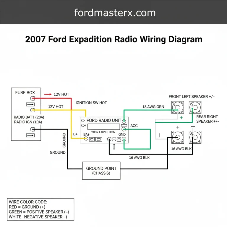
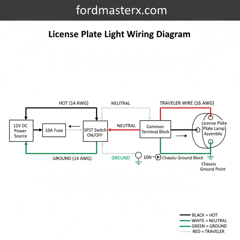
A license plate light wiring diagram serves as a blueprint for the low-voltage DC circuit that powers your rear exterior lighting. At its core, the system is designed to provide a steady 12-volt flow to the bulb whenever the parking lights or headlights are activated. The diagram typically illustrates the path starting from the fuse box, moving through a relay or switch, and terminating at the bulb socket located near the rear bumper.
The primary components in this circuit include the hot wire, which carries the positive charge, and the ground wire, which completes the circuit by connecting back to the vehicle chassis. In the diagram, the hot wire is often represented by a solid color (commonly red or brown), while the ground is depicted as black or green. You will also notice a common terminal within the light housing; this is the point where the electrical load is distributed to the filament or LED chip. If your vehicle utilizes a multi-function lighting harness, you might see a traveler wire. This specific wire acts as the bridge between the primary lighting switch and the rear distribution block, ensuring that the license plate light illuminates in synchronization with your tail lights.
The diagram also specifies the gauge of the wire used. For license plate circuits, which draw very little current, a thin 18-gauge or 16-gauge wire is standard. Thicker wires are unnecessary because the voltage remains a consistent 12V to 14V (when the engine is running), and the amperage is minimal. Understanding the distinction between the brass screw terminals on aftermarket sockets and the pin-out connectors on OEM harnesses is vital for a successful installation.
Most automotive diagrams use standardized symbols. A series of parallel lines of decreasing length represents the ground connection, while a circle with a cross inside typically represents the light bulb itself. Always verify your specific vehicle’s color code, as manufacturers like Ford, GM, and Toyota may use different colors for the hot and neutral wire equivalents.
Step-by-Step Guide to Interpreting and Installing Wiring
To successfully use a license plate light wiring diagram for installation or repair, follow this logical sequence. This ensures safety and prevents accidental short circuits that could damage your vehicle’s Body Control Module (BCM).
Step 1: Disconnect the Power Source
Before touching any part of the electrical system, disconnect the negative terminal from your vehicle battery. This eliminates the risk of sparking if a hot wire accidentally touches the metal frame.
Step 2: Locate the Wiring Harness
Find the wiring harness that leads to the rear license plate area. Use your diagram to identify the specific traveler wire that branches off from the main tail light loom. This wire is responsible for delivering the 12V signal when the lights are turned on.
Step 3: Identify the Terminals
Examine your light socket. In many aftermarket or universal kits, you will find a brass screw and a silver screw. The brass screw is designated for the hot wire (positive), while the silver screw is typically for the neutral wire or ground connection. If you are using a plug-and-play OEM connector, identify the pin numbers based on the diagram provided by the manufacturer.
Step 4: Prepare the Wires
Using a wire stripper, remove approximately half an inch of insulation from both the hot wire and the ground wire. Ensure you are using the correct gauge for your crimp connectors to ensure a tight, vibration-resistant seal.
Step 5: Establish the Ground Connection
A common failure point is a weak ground. Connect the ground wire from the socket to a clean, unpainted part of the vehicle’s metal chassis. If the diagram shows a dedicated ground wire returning to the harness, splice it into the existing neutral wire path.
Step 6: Connect the Positive Lead
Connect the traveler wire (the hot wire from the switch) to the common terminal of the license plate light. If you are wiring multiple lights (common in trucks), ensure they are wired in parallel, not in series, to maintain consistent voltage across both bulbs.
Step 7: Insulate and Secure
Use heat-shrink tubing or high-quality electrical tape to cover all connections. This prevents moisture from causing corrosion, which is especially important since license plate lights are exposed to road spray and debris. Secure the harness with zip ties to prevent it from dangling or rubbing against sharp metal edges.
Step 8: Final Testing
Reconnect the battery. Turn on your parking lights and walk to the rear of the vehicle. Use a multimeter to verify that you have approximately 12.6V at the socket if the light fails to illuminate. This confirms that the voltage is reaching the terminal and that your ground path is solid.
Never replace a blown license plate light fuse with one of a higher amperage. If the diagram specifies a 5A fuse, using a 10A or 15A fuse can cause the wiring to overheat and melt before the fuse blows, potentially leading to an electrical fire.
Common Issues and Troubleshooting the Circuit

When a license plate light fails, the license plate light wiring diagram becomes your primary diagnostic tool. The most frequent issue is a broken ground wire. Because the rear of the vehicle is susceptible to moisture and road salt, the connection between the ground wire and the chassis often oxidizes. If your diagram shows a ground point on the frame, start by cleaning that contact area with a wire brush.
Another common problem is a “phantom” voltage drop. This occurs when the hot wire has internal corrosion or a partial break. You might measure 12V with a multimeter, but the bulb still appears dim or flickers. In this case, the traveler wire may be compromised somewhere along the chassis rail. By following the diagram from the rear bumper back toward the front of the car, you can inspect the harness for pinch points or heat damage from the exhaust system.
If both license plate lights are out, the issue is likely “upstream” in the circuit. Check the common terminal at the fuse block or the relay that controls the rear illumination. If the fuse is intact but no power reaches the rear, the switch or the traveler wire itself may be disconnected.
- ✓ Flickering lights: Usually indicates a loose ground wire or a vibrating common terminal.
- ✓ Dim lights: Often caused by high resistance due to undersized wire gauge or corrosion.
- ✓ No power: Suggests a blown fuse or a break in the hot wire path.
Tips and Best Practices for Long-Lasting Wiring
To ensure your wiring job stands the test of time, always prioritize environmental protection. The area behind the license plate is one of the harshest environments for electrical components. Using marine-grade heat-shrink connectors is a superior choice compared to standard plastic butt connectors. These specialized connectors contain an adhesive that melts when heated, creating a waterproof seal around the wire gauge.
When choosing replacement bulbs, consider switching to LEDs. LEDs draw significantly less current and run cooler than traditional incandescent bulbs, which reduces the thermal stress on the socket and the hot wire. However, some modern vehicles may interpret the lower power draw as a “bulb out” error. In these cases, your wiring diagram may need to be modified to include a load resistor between the hot wire and the ground wire to simulate the resistance of an incandescent bulb.
Apply a small amount of dielectric grease to the bulb base and the brass screw terminals before final assembly. This non-conductive grease prevents moisture from reaching the metal surfaces, effectively stopping corrosion before it starts.
Maintenance is also key. Once a year, inspect the harness for any signs of sagging. If the traveler wire or ground wire is hanging too low, it can snag on road debris. Always use UV-rated zip ties to keep the wiring tucked neatly against the frame. By following the original license plate light wiring diagram and adhering to these professional standards, you can ensure your vehicle’s rear lighting is reliable, bright, and fully compliant with all safety regulations. Professional-grade results are achievable for any DIYer who takes the time to map out their circuit and use quality materials designed for automotive use.
Frequently Asked Questions
Where is the license plate light located?
These lights are positioned above or to the sides of the rear registration plate on the trunk lid or bumper. They are designed to illuminate the plate clearly from a distance. Accessing them usually involves removing a plastic lens cover or reaching behind the bumper assembly to find the wiring.
What does a license plate light wiring diagram show?
This diagram provides a visual map of the electrical circuit, showing how the hot wire delivers power from the fuse box to the light. It also identifies the neutral wire or ground wire path, ensuring the circuit is complete and the bulb illuminates when the vehicle headlights are active.
How many wires does a license plate light have?
Most standard license plate lights utilize a simple two-wire system. One is the hot wire, which provides 12V power when the parking lights are switched on, and the other is the ground wire, which connects to the vehicle chassis or a common terminal to complete the electrical circuit.
What are the symptoms of a bad license plate light?
Common symptoms include a completely dark bulb, flickering light, or dim illumination. If a new bulb doesn’t work, there may be a break in the traveler wire, a loose common terminal connection, or significant corrosion inside the socket that prevents proper electrical contact from occurring with the bulb.
Can I replace the license plate light wiring myself?
Yes, replacing or repairing this wiring is a straightforward DIY task. By following a wiring diagram, you can easily identify the hot and ground connections. Basic splicing and crimping skills are required to ensure the new wires are secure and properly weatherproofed against moisture and harsh road debris.
What tools do I need for this wiring task?
You will need a screwdriver or trim tool to remove the light housing, a wire stripper for preparing connections, and a multimeter to test for power. Heat-shrink tubing and electrical tape are also essential for protecting the wiring from environmental damage and ensuring long-lasting, safe electrical repairs.