Ignition Switch Wiring Color Code: Identification Standards For Automotive Electrical Circuits
In the world of automotive electrical diagnostics, the ignition switch acts as the primary gateway for vehicle operation, yet its complex harness often remains a mystery to many. Whether you are performing a restoration, installing an aftermarket security system, or troubleshooting a “no-start” condition, understanding the logic behind the wires is paramount. Mistaking a constant power wire for a switched ignition lead can result in parasitic battery drain, blown fuses, or catastrophic electrical fires. This guide provides an authoritative breakdown of the ignition switch wiring color code standards, manufacturer-specific variations, and the professional testing protocols required for a trusted repair.
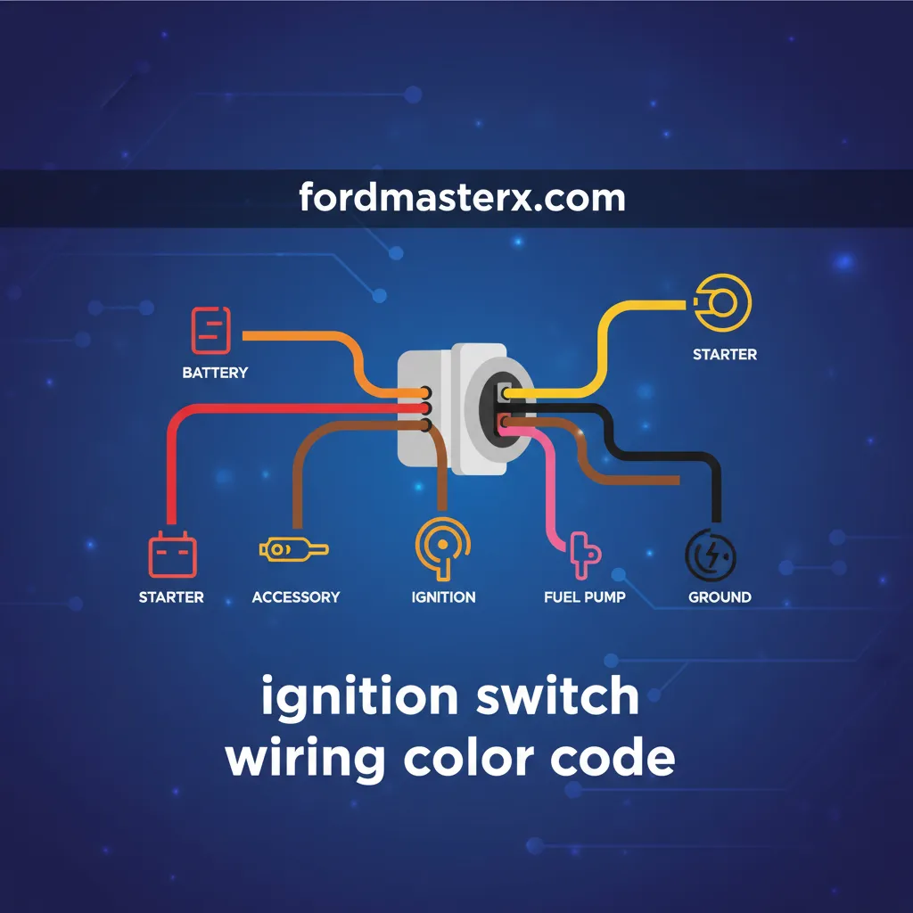
Understanding Standard Ignition Switch Wiring Color Code Functions and Terminal Markings

📤 Share Image
To master automotive circuitry, one must first recognize that the ignition switch is a multi-stage rotary or electronic distributor of electrical current. While colors vary by manufacturer, the Bosch terminal numbering system remains the global benchmark for identifying circuit functions. This system ensures that technicians can navigate complex schematics across different platforms with a comprehensive understanding of the electrical flow.
The Constant Power Source (Terminal 30 or B)
The Battery (B) or Terminal 30 wire is the “unswitched” source. It maintains a 12V charge directly from the battery (often via a fusible link or high-amp fuse) regardless of the key position. In most domestic and European vehicles, this wire is Red. Its primary role is to provide the raw current that the ignition switch will later distribute to other subsystems. A failure here results in a completely “dead” switch, where no position—ACC, Run, or Start—yields any electrical activity.
The Ignition/Run Circuit (Terminal 15)
Terminal 15, commonly referred to as the Ignition (IGN) wire, is a “switched” power source. It only becomes “hot” when the key is turned to the ‘Run’ and ‘Start’ positions. This circuit is critical because it energizes the Engine Control Module (ECM), fuel pump relay, and ignition coils. Expert technicians know that the Terminal 15 circuit must remain energized during the cranking phase to ensure the engine actually fires. If power drops out during cranking, the engine will turn over but never start.
The Accessory Circuit (Terminal 75 or ACC)
The Accessory wire powers non-essential systems like the radio, wipers, and blower motor. Unlike the Ignition circuit, the ACC circuit is typically disconnected during the cranking (Start) phase to prioritize all available battery amperage for the starter motor. This is why your radio cuts out momentarily when you start your car. Identifying this wire is essential when installing aftermarket accessories to prevent them from drawing power when the vehicle is off.
The Starter Signal (Terminal 50 or ST)
The Starter (ST) wire, or Terminal 50, is a momentary circuit. It only receives power when the key is held in the ‘Start’ position. This wire sends a low-current signal to the starter solenoid, which then closes a high-current bridge to engage the starter motor. In domestic applications, this is frequently a Purple or Yellow wire. Because this circuit carries the signal that initiates mechanical movement, any high resistance here will lead to a “click-no-start” scenario.
Standard Terminal Designations
Constant 12V (+)
Switched Ignition
Starter Solenoid
Accessory (ACC)
Manufacturer Variations in Ignition Wiring Color Protocols and Harness Design
While the functional logic remains consistent, automotive manufacturers employ vastly different color palettes. Relying on a complete understanding of these variations is what separates a DIYer from a professional. Without a factory service manual (FSM), a technician must fall back on established brand-specific patterns.
General Motors (GM) and Ford Standards
For decades, General Motors utilized a highly consistent color scheme. Red serves as the primary battery feed, Pink handles the main ignition/run circuit, and Purple is the starter signal. In contrast, Ford Motor Company often utilizes Yellow for constant power and Red/Light Green for the primary ignition circuit. It is common to see Grey or Black/Light Green for Ford accessory circuits, showcasing how even domestic brands can differ significantly.
Asian Import Specifications (Toyota and Honda)
Japanese vehicles often deviate from the “Red for Power” rule. Over 70% of Japanese vehicles utilize a White or White/Red primary ignition feed. For Toyota and Honda, the starter wire is frequently Black/White. This shift in protocol requires a trusted approach where the technician does not make assumptions based on domestic habits. For instance, in a 2010s Toyota Camry, the ignition circuit is vastly different in gauge and color than a 1990s Chevrolet Silverado, reflecting advancements in multiplexing and lower-current switching.
Dealing with ‘Ghost’ Colors and Faded Insulation
In vintage automotive applications, colors can fade due to heat and age. A once-vibrant Pink wire may look White or Tan after thirty years of engine heat. This is where quality diagnostics become crucial. Always peel back the loom or electrical tape to find a section of wire protected from the elements to verify the true base color and stripe. If you encounter “vampire taps” (insulation-piercing connectors) from previous owners, treat those circuits as compromised and inspect for internal copper corrosion.

Diagnostic Tools and Safety Procedures for Verifying Ignition Circuits
Before making a single connection, you must verify the circuit’s behavior. In my 15+ years of experience, I have seen modern Engine Control Units (ECUs) destroyed by technicians using old-fashioned incandescent test lights. Modern vehicle electronics require a professional-grade approach to testing.
Always use a Digital Multimeter (DMM) with at least 10 Megohms of input impedance. Lower-quality meters or test lights can draw enough current to trigger sensitive transistors in the ECU, potentially causing permanent hardware failure.
📋
Circuit Verification Guide
With the key removed, probe the harness wires. The wire that shows ~12.6V is your main feed. Reliable diagnostics start here.
Turn the key to ‘ACC’. Identify the powered wire. Then turn to ‘Run’. The ACC wire should stay hot, and a second wire (Ignition) will now show 12V.
While monitoring the remaining wires, turn the key to ‘Start’. The wire that shows voltage ONLY during cranking is your starter lead.
Safety and Load Testing
A common pitfall is testing for voltage but failing to test for amperage capacity. A corroded wire can show 12V on a multimeter but fail to deliver enough current to engage a relay. If you suspect high resistance, perform a voltage drop test. Furthermore, always disconnect the negative battery terminal before cutting or splicing into the main ignition harness to prevent accidental short circuits to the steering column ground.
Never probe wires in the steering column yellow-sleeved harness. These are Airbag (SRS) circuits. Accidentally applying current or grounding these wires can cause immediate airbag deployment and severe injury.
Professional Wiring Standards for Reliable Ignition System Maintenance
Once the wires are identified, the method of connection determines the long-term reliability of the repair. Ignition circuits handle significant current, often ranging from 10 to 30 amps before reaching their respective relays. Substandard connections are the number one cause of intermittent starting issues and electrical “gremlins.”
Choosing the Right Gauge and Connectors
Most primary ignition feeds utilize 10 to 14 AWG (American Wire Gauge) wire. Using a wire that is too thin will create resistance, leading to heat buildup and a potential fire hazard. For connections, expert mechanics avoid plastic “butt” crimps. Instead, use heat-shrink adhesive-lined crimp connectors or, ideally, a Western Union splice followed by soldering and marine-grade heat shrink. This creates a vibration-resistant, airtight seal that prevents oxygen from oxidizing the copper.
✅ Recommended Practices
- Use 10-14 AWG for primary feeds
- Heat-shrink insulation for every joint
- Ratcheting crimp tools for consistent pressure
- Apply dielectric grease to terminal faces
- Loom and secure wires away from steering movement
❌ Avoid These Errors
- Standard electrical tape (peels over time)
- Twist-and-tape “quick fixes”
- Undersized wire gauges (creates heat)
- Routing wires near sharp metal edges
- Tapping into SRS/Airbag looms
Voltage Drop and EMI Management
After finalizing your wiring, perform a voltage drop test while the circuit is under load. A high-quality junction should show no more than a 0.2V drop across the connection. Anything exceeding 0.5V indicates a high-resistance point that will lead to premature starter solenoid failure or intermittent ECM reset issues. Furthermore, ensure proper looming to mitigate Electromagnetic Interference (EMI), which can disrupt sensitive crank position sensor signals if the high-current starter wires are bundled too tightly with low-voltage signal wires.
Reliable Conductivity
Soldered connections ensure 0% chance of vibration-induced decoupling in heavy-duty environments.
Weather Resistance
Adhesive-lined heat shrink prevents wicking of moisture, which is the primary cause of internal wire rot.
Accurate identification of Battery, Ignition, Accessory, and Starter wires is critical for maintaining vehicle system integrity. As we have explored, manufacturer-specific color codes vary significantly and must be verified with a high-impedance multimeter before any installation or repair occurs. Utilizing professional-grade tools, such as ratcheting crimpers and heat-shrink connectors, ensures a reliable and safe electrical repair that will withstand the vibration and thermal cycles of an automotive environment. Always consult your vehicle’s specific factory service manual and prioritize safety by verifying all circuits before finalizing your ignition switch wiring project. With the right methodology, even the most complex harness becomes manageable and secure.
Frequently Asked Questions
What color is the ignition wire usually?
While it varies by manufacturer, the ‘Run’ ignition wire (Terminal 15) is most commonly Pink in GM vehicles, Red/Green in Fords, and Black/Yellow in many Honda and Toyota models. You must always use a multimeter to verify that the wire shows 12V only when the key is in the ‘On’ and ‘Start’ positions.
Can I use the accessory wire for a remote start installation?
No, the accessory wire (ACC) typically loses power during the cranking phase to provide maximum amperage to the starter motor. For a remote start system, you must tap into the primary Ignition (IGN) wire, which maintains power during both the ‘Run’ and ‘Start’ cycles to keep the engine management system active.
Why does my ignition switch have two red wires?
Many high-draw systems utilize dual constant power feeds to distribute the electrical load and prevent overheating of the switch contacts. In professional applications, both wires should be tested to ensure they originate from the same fused source and maintain 12V at all times, even when the vehicle is off.
Is there a universal color code for all cars?
Unfortunately, there is no universal color code across the automotive industry. While many aftermarket radio harnesses follow the EIA standard, vehicle manufacturers use proprietary color schemes. Always refer to a trusted wiring diagram for your specific year, make, and model to ensure accurate circuit identification.
What is the ‘ST’ terminal on an ignition switch?
The ‘ST’ or ‘Start’ terminal (Terminal 50) is the circuit responsible for engaging the starter solenoid. This wire only receives 12V power when the key is turned to the ‘Crank’ position. It is usually a thicker gauge wire, such as 10 or 12 AWG, to handle the momentary surge required for engagement.