Ignition Coil B Primary/Secondary Circuit: Complete Guide
A sudden stumble during acceleration or a persistent “Check Engine” light can transform a routine drive into a stressful diagnostic puzzle. When your OBD-II scanner returns a code regarding the Ignition Coil B Primary/Secondary Circuit, it is signaling a breakdown in the very heart of your engine’s combustion process. This specific fault doesn’t just impact performance; it threatens the long-term health of your catalytic converter and engine internals. Understanding how “Coil B”—typically associated with cylinder number two—operates is the first step toward a professional-grade repair that saves both time and money. This comprehensive guide will navigate the intricacies of ignition electronics, moving beyond basic part-swapping to true technical mastery.
Overview: Decoding the “Coil B” Architecture
In modern Coil-on-Plug (COP) or Waste Spark systems, the Engine Control Module (ECM/PCM) manages ignition timing by controlling individual coils. “Coil B” specifically refers to the second coil in the firing order or the coil designated for cylinder #2. To understand a circuit failure here, one must differentiate between the two distinct but interconnected halves of the coil’s operation.

📤 Share Image
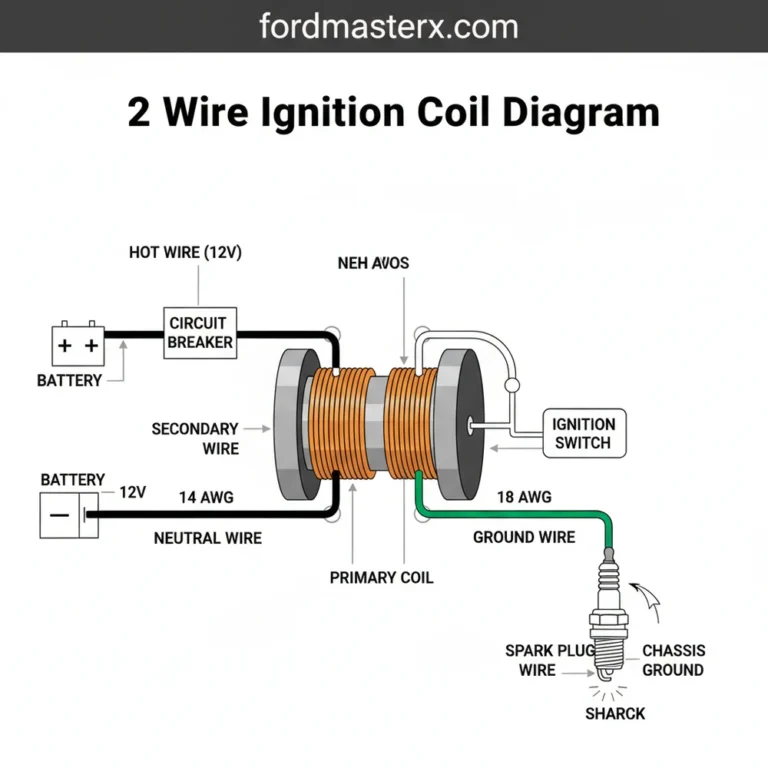
The Primary Circuit: The Low-Voltage Trigger
The primary circuit is the “command” side of the system. It typically consists of a 12-volt power feed from the ignition relay and a ground wire that leads back to the PCM. The PCM acts as a high-speed switch, opening and closing the ground circuit to build a magnetic field within the coil. If the PCM detects that the current flow in this circuit is too high, too low, or non-existent, it triggers a trusted diagnostic trouble code (DTC) like P0352.
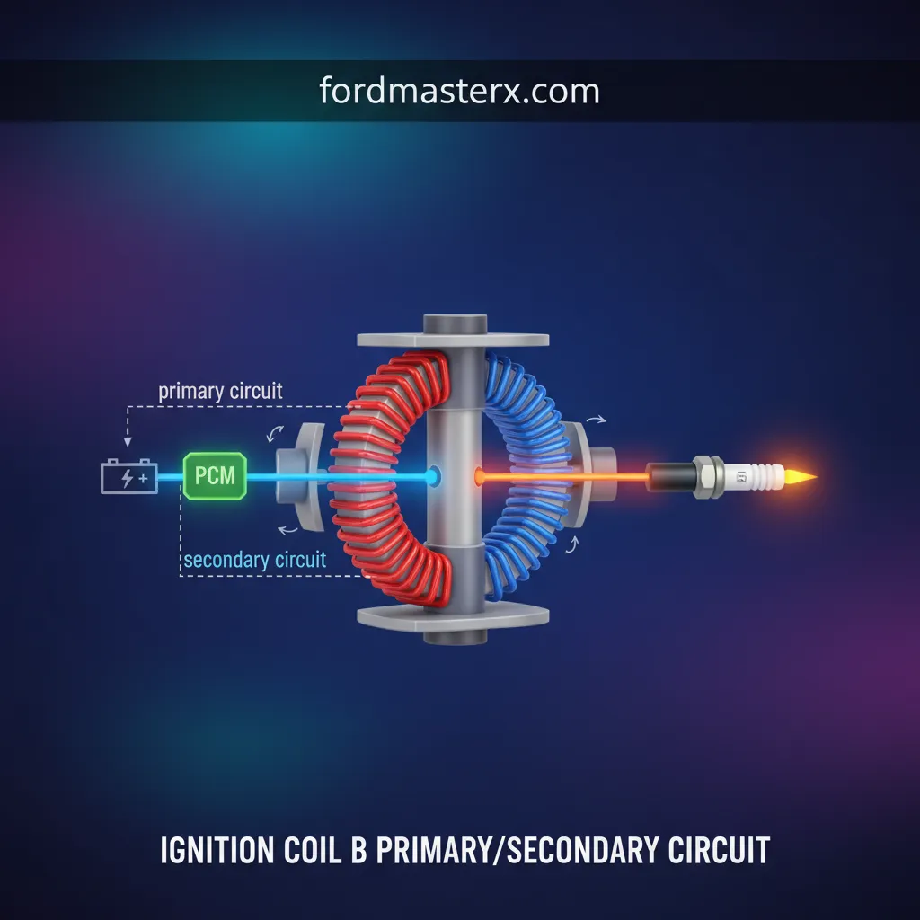
The Secondary Circuit: The High-Voltage Discharge
The secondary circuit is the “output” side. When the PCM abruptly breaks the primary ground, the magnetic field collapses, inducing a massive voltage spike (often 20,000 to 50,000 volts) in the secondary windings. This high voltage travels through the coil boot to the spark plug. A failure in the secondary circuit—such as carbon tracking, a cracked housing, or a fouled plug—often reflects back into the primary side, causing the PCM to register a circuit malfunction.
By The Numbers
Approximate Primary/Secondary Wire Ratio
Standard Primary Input Voltage
Max Secondary Output Capability

Key Benefits of Proper Circuit Maintenance
Addressing a “Coil B” issue immediately rather than letting the vehicle “limp” along provides significant advantages for the vehicle owner. Ignoring a primary or secondary circuit fault leads to raw fuel being dumped into the exhaust, which is the primary cause of expensive component failure.
Optimized Fuel Economy
A complete spark ensures total combustion, preventing fuel waste and maintaining your MPG ratings.
Catalytic Converter Protection
Misfires cause unburned fuel to ignite inside the converter, leading to thermal meltdown and high repair costs.
Smooth Engine Operation
Restoring Coil B eliminates vibrations, hesitation, and stalling, providing a reliable and professional driving experience.
How It Works: The Science of Induction
The ignition coil is essentially a step-up transformer. It operates on the principle of mutual electromagnetic induction. Inside the coil housing, two sets of copper windings are wrapped around a common iron core. The primary winding has relatively few turns of heavy-gauge wire, while the secondary winding consists of thousands of turns of very fine wire.
When the ignition is on, 12V is supplied to the primary winding. The PCM provides a ground, allowing current to flow and creating a strong magnetic field. To fire the spark, the PCM “interrupts” the ground. This abrupt stoppage causes the magnetic field to collapse almost instantly across the secondary windings. Because of the massive difference in the number of wire turns (the turns ratio), the low voltage is transformed into the high voltage necessary to jump the gap of the spark plug under the intense pressure of the combustion chamber.
Getting Started: Professional Diagnostic Steps
When faced with a circuit malfunction code, a complete guide to resolution involves more than just buying a new part. Use this expert-verified workflow to isolate the root cause accurately.
📋
Step-by-Step Diagnostic Guide
Inspect the wiring harness leading to Coil B. Look for frayed wires, melted insulation, or corrosion in the connector pins. Often, engine heat makes the plastic connectors brittle, leading to poor contact.
This is the expert’s shortcut. Swap Coil B with Coil A. Clear the codes and run the engine. If the code moves (e.g., changes from P0352 to P0351), the coil is defective. If the code stays at B, the issue is in the wiring or the PCM.
Using a Digital Multimeter (DMM), measure the ohms between the primary pins. Most COP systems should show 0.5 to 2.0 ohms. High resistance indicates a failing internal winding; “OL” or infinite resistance indicates an open circuit.
Never test for spark by pulling the coil boot off and holding it near a ground while the engine is cranking. Modern ignition systems can generate enough voltage to damage the PCM or deliver a dangerous electrical shock to the technician. Use a dedicated spark tester tool.
Advanced Troubleshooting: Signal Verification
If the coil tests within specifications but the circuit code remains, you must verify the signals reaching the coil. A reliable diagnosis requires checking for “switching.” Using a 12V test light connected to the positive battery terminal, touch the ground trigger pin on the coil connector while cranking. If the light flickers, the PCM is successfully switching the circuit. If it stays off or remains solid, there is a break in the wiring harness or a failed driver inside the PCM itself.
Always pull the spark plug for Cylinder B when diagnosing a circuit code. Look for thin, black “lightning bolt” lines on the white porcelain. This is carbon tracking—a path where high voltage has leaked to the ground, often mimicking a coil failure when the actual culprit is a worn spark plug.
Pros and Cons of Replacement Strategies
When it comes to the repair stage, you are faced with a choice: replace only the failed coil or replace the entire set. Each approach has its merits depending on the vehicle’s mileage and the owner’s budget.
✅ Pros of Full Replacement
- Ensures uniform resistance across all cylinders
- Prevents “cascading failures” where other old coils fail weeks later
- Resets the maintenance clock for the entire ignition system
- Peace of mind for long-distance driving
❌ Cons of Single Replacement
- Potential for mismatched performance characteristics
- Increased likelihood of another breakdown soon
- Does not address age-related degradation in other coils
- Labor costs are often higher if you have to return to the shop
Common Pitfalls in Ignition Circuit Repair
In my 15+ years of industry experience, the most common mistake made by technicians is assuming the coil itself is the only possible failure point. A professional knows that the ignition system is a complete loop. If the spark plug gap has widened excessively over 100,000 miles, the coil must work significantly harder to jump that gap. This increased demand generates heat, which eventually burns out the internal secondary windings of the coil. Replacing the coil without replacing the worn spark plugs is merely a “band-aid” fix that will likely lead to a repeat failure within months.
Another nuance involves Electro-Magnetic Interference (EMI). Cheap, non-OEM coils often lack the shielding required to prevent electrical noise from interfering with the PCM’s sensitive logic. This can result in phantom codes, erratic idle, and even transmission shifting issues. Always prioritize trusted, high-quality components from reputable manufacturers when dealing with ignition electronics.
Summary and Expert Recommendations
Diagnosing an Ignition Coil B Primary/Secondary Circuit fault requires a disciplined approach to separate the coil, the wiring, and the controller. By understanding that the primary circuit triggers the event and the secondary circuit delivers the results, you can use simple tools like a multimeter and the “swap test” to pinpoint the failure with surgical precision.
- Key Point 1: Always verify the physical integrity of the connector and wiring harness before condemning the coil.
- Key Point 2: Use the “Swap Test” to quickly determine if the fault is internal to the coil or external in the vehicle’s circuitry.
- Key Point 3: Replace spark plugs alongside a failed coil to ensure the new component isn’t subjected to immediate electrical stress.
If your vehicle is currently displaying a P0352 or similar code, don’t wait for a total breakdown. Perform a resistance test today or consult a professional to ensure your ignition system remains reliable and efficient. Taking action now preserves your engine’s power and prevents costly downstream repairs.