Full Engine Ford 4.9 Engine Diagram: Identification Guide
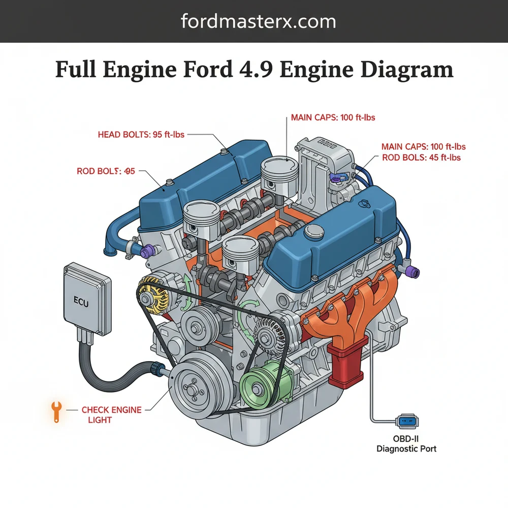
A full engine Ford 4.9 engine diagram illustrates the iconic inline-six layout, detailing the intake manifold, accessory drive, and cylinder head configuration. This guide helps users identify critical sensor locations and components connected to the ECU. It is essential for locating vacuum lines and ensuring every bolt meets the correct torque spec.
📌 Key Takeaways
- Visualizes the layout of the durable 300 cubic inch inline-six engine
- Identifies the placement of the ECU and associated engine sensors
- Highlights critical vacuum line routing to prevent rough idling
- Provides a reference for maintaining the correct torque spec on head bolts
- Simplifies the identification of components for faster troubleshooting
Finding a reliable full engine ford 4.9 engine diagram is a critical first step for any owner or mechanic working on the legendary Ford 300 cubic-inch inline-six. Whether you are performing a complete overhaul, replacing a single sensor, or simply trying to understand the routing of your accessory belt, having a visual roadmap is essential. This engine, renowned for its industrial-grade durability and “bulletproof” reputation, features a unique architecture that differs significantly from more common V8 configurations. In this guide, we will break down the entire engine assembly, identify key components, and provide the technical context needed to interpret diagnostic codes and maintenance requirements effectively. By the end of this article, you will have a comprehensive understanding of the 4.9L powerplant and how to use its technical diagrams to keep your vehicle on the road for hundreds of thousands of miles.
Understanding the Architecture: Main Diagram Description
The 4.9L Ford engine is a cast-iron, seven-main-bearing, inline-six-cylinder engine. When looking at a full engine ford 4.9 engine diagram, the first thing you will notice is the “long” profile of the block. Unlike a V-style engine, all six cylinders are arranged in a straight line, which places the intake and exhaust manifolds on the same side of the cylinder head (the driver’s side). This “non-crossflow” design is a defining characteristic of the 300 inline-six.
The diagram typically breaks the engine down into several sub-systems. On the front of the engine, you will see the accessory drive system, which includes the alternator, power steering pump, and air conditioning compressor. Depending on the specific year of your engine, the diagram will show either a V-belt setup or a single serpentine accessory belt. The lower front section houses the timing gear cover. A unique feature of the 4.9L is that it traditionally uses timing gears rather than a timing chain, providing incredible longevity, though many diagrams still refer to this as the timing set area.
The side profile of the diagram highlights the fuel delivery system. On later fuel-injected models, the upper intake plenum is a large, distinctive aluminum casting that sits atop the engine. Below this, the diagram should label the ECU (Engine Control Unit) sensors, including the MAP (Manifold Absolute Pressure) sensor, the Throttle Position Sensor (TPS), and the Idle Air Control (IAC) valve. Understanding these locations is vital for interpreting a diagnostic code when the check engine light appears on your dashboard.
The Ford 4.9L engine is famous for its low-end torque. Most diagrams will show the peak torque being achieved at very low RPM (often around 1600-2000 RPM), which is why it was the preferred choice for heavy-duty work trucks and vans for decades.
Step-by-Step Guide: How to Read and Apply the Diagram

Interpreting an automotive diagram can be overwhelming if you don’t know where to start. Follow these steps to use your full engine ford 4.9 engine diagram for repair or identification.
Step 1: Orient the Engine Diagram
Begin by identifying the “front” of the engine on the diagram, which is where the cooling fan and pulleys are located. On the 4.9L, the number one cylinder is always at the front, closest to the radiator. This orientation is crucial for tasks like setting the firing order or adjusting valves.
Step 2: Trace the Accessory Belt Routing
If you are replacing a belt, look for the accessory belt path in the diagram. It will show the correct wrap pattern around each pulley. Ensure the belt passes over the tensioner correctly; failing to follow the diagram can result in the water pump rotating in the wrong direction, leading to immediate overheating.
Step 3: Locate the Cooling System Components
Trace the coolant flow through the diagram. On the 4.9L, the thermostat housing is located at the top front of the cylinder head. The diagram will show the flow path from the lower radiator hose, through the water pump, into the block, up through the head, and out through the thermostat. This is essential for bleeding air out of the system.
Step 4: Identify Electrical and ECU Sensors
For troubleshooting, find the sensor locations on the diagram. Look for the Engine Coolant Temperature (ECT) sensor and the Oxygen (O2) sensors. If your vehicle is equipped with OBD-II (generally models from the mid-90s), the diagram will also indicate the location of the data link connector where you plug in your scanner to read a diagnostic code.
Step 5: Review Torque Specs and Fasteners
A comprehensive diagram often includes a table for the torque spec of critical bolts. For the 4.9L, the cylinder head bolts must be tightened in a specific sequence to prevent warping. The diagram will show a numbered pattern, usually starting from the center and spiraling outward.
Always disconnect the negative battery terminal before performing any work identified in the electrical or ECU sections of the diagram. Shorting out the 4.9L engine’s wiring harness can damage the ECU beyond repair.
Required Tools for Application:
- ✓ Socket set (standard and metric, though older 4.9s are primarily SAE)
- ✓ Calibrated torque wrench
- ✓ OBD-II or OBD-I scanner (depending on year)
- ✓ Multimeter for testing sensor voltage
- ✓ Feeler gauges for valve lash or spark plug gaps
Common Issues and Troubleshooting with the 4.9L

Even an engine as reliable as the Ford 4.9 is prone to specific issues over time. The diagram becomes your best friend when the check engine light illuminates. One of the most common problems is a vacuum leak, often occurring in the complex web of hoses connected to the intake manifold. Using the vacuum routing portion of the diagram allows you to check each connection point systematically.
Another frequent issue involves the exhaust manifold. Because the manifold is very long, it is subject to significant thermal expansion and contraction, which can lead to cracks or broken manifold bolts. A diagram helps you identify which bolts are most likely to fail and shows the correct sequence for removal. If your ECU triggers a diagnostic code related to a “lean condition,” the diagram will help you locate the PCV valve or the EGR valve, both of which are common culprits for unmetered air entering the system.
If you are experiencing a rough idle but no check engine light, use the diagram to locate the Idle Air Control (IAC) valve on the side of the throttle body. Often, cleaning this component with specialized cleaner can restore a smooth idle without needing a replacement.
Maintenance Tips and Best Practices
To get the most out of your Ford 300 inline-six, following best practices for maintenance is non-negotiable. While the timing gears are designed to last the life of the engine, the accessory belt and pulleys are wear items. Inspect the belt for cracking every 30,000 miles, using your diagram to ensure the tensioner is providing adequate pressure.
When it comes to the cooling system, the 4.9L has a large internal volume. Ensure your coolant flow remains unobstructed by flushing the system every two years. Use the diagram to find the block drain plugs, which are often overlooked but necessary for a complete flush. Furthermore, always adhere to the specific torque spec for the spark plugs and valve cover bolts. Over-tightening the valve cover is a common mistake that leads to oil leaks on the passenger side of the block.
Lastly, invest in high-quality gaskets. Because the intake and exhaust share a gasket surface on the cylinder head, using a premium multi-layer steel or heavy-duty composite gasket is vital for preventing leaks. If you are doing a rebuild, pay close attention to the timing gear alignment marks shown in the diagram; although there is no timing chain to stretch, the gears must be indexed perfectly to maintain correct valve timing.
By using a full engine ford 4.9 engine diagram as your primary reference, you can demystify the complexities of this classic engine. From understanding the logic of the ECU to ensuring the coolant flow is optimal, a good diagram transforms a daunting repair into a manageable DIY project. Keep your diagnostic tools handy, follow the torque specifications strictly, and this Ford engine will likely outlast the vehicle it’s bolted into.
Frequently Asked Questions
Where is the ECU located on a Ford 4.9 engine?
On most Ford trucks equipped with the 4.9 engine, the ECU is located behind the firewall on the driver’s side or tucked behind the interior kick panel. The diagram helps you trace the wiring harness from the engine sensors directly back to this control module for electrical testing.
What does a full engine Ford 4.9 engine diagram show?
This diagram displays the complete assembly of the 4.9L inline-six, including the intake and exhaust manifolds, cooling system, and belt-driven accessories. It also maps out the vacuum system and electrical sensor locations, which are vital for maintaining the engine’s legendary reliability and performance over time.
How many vacuum connections does the Ford 4.9 have?
The Ford 4.9 engine features several critical vacuum connections located primarily on the upper intake manifold. These lines support the EGR valve, brake booster, and MAP sensor. Referring to a diagram is essential because a single disconnected line can trigger a check engine light and cause stalling.
What are the symptoms of a sensor failure on this engine?
Common symptoms include a sudden check engine light, poor fuel economy, or a rough idle. If your OBD-II scanner reveals a specific diagnostic code, use the diagram to locate the failing sensor, such as the coolant temp sensor or TPS, to test its resistance and wiring integrity.
Can I perform a top-end rebuild using this diagram?
Yes, you can certainly perform a top-end rebuild using this diagram to identify part locations and assembly order. However, you must also use a dedicated service manual to find the exact torque spec for the cylinder head bolts and manifold nuts to ensure a leak-free seal.
What tools do I need for Ford 4.9 engine diagnostics?
For effective diagnostics, you will need an OBD-II code reader for 1996 models or an EEC-IV reader for older versions. Additionally, a vacuum gauge, a digital multimeter for testing ECU signals, and a torque wrench for reassembly are required to properly address any diagnostic code you encounter.


