Fuel Tank Selector Valve Diagram: Routing & Setup Guide
A fuel tank selector valve diagram illustrates the electrical and plumbing connections used to switch between two fuel tanks. It details how the dash switch sends signals to the valve motor, which redirects fuel lines and sender signals. This visual guide is essential for diagnosing switching failures and ensuring the ECU receives correct fuel level data.
📌 Key Takeaways
- Identifies the routing for supply and return fuel lines
- Shows electrical pinouts for the tank-switching motor
- Essential for preventing fuel cross-filling between tanks
- Helps locate the ground and power wires for the selector
- Used when the fuel gauge fails to switch between tanks
Understanding your vehicle’s fuel delivery system is essential for maintaining performance and safety, particularly in trucks and heavy-duty vehicles equipped with dual reservoirs. Navigating the complexities of a fuel tank selector valve diagram allows you to visualize how fuel travels from separate tanks to your engine without manual intervention. Whether you are dealing with a faulty switch or a complete blockage, having an accurate diagram prevents costly routing errors and electrical mishaps. This article will provide you with a detailed breakdown of the valve’s architecture, electrical integration, and a comprehensive guide to diagnosing and replacing this critical component.
The fuel tank selector valve is an electromechanical device. It uses a motorized actuator or a solenoid to toggle between the main and auxiliary tanks, controlled by a dash-mounted switch or the vehicle’s engine control module.
Decoding the Fuel Tank Selector Valve Diagram
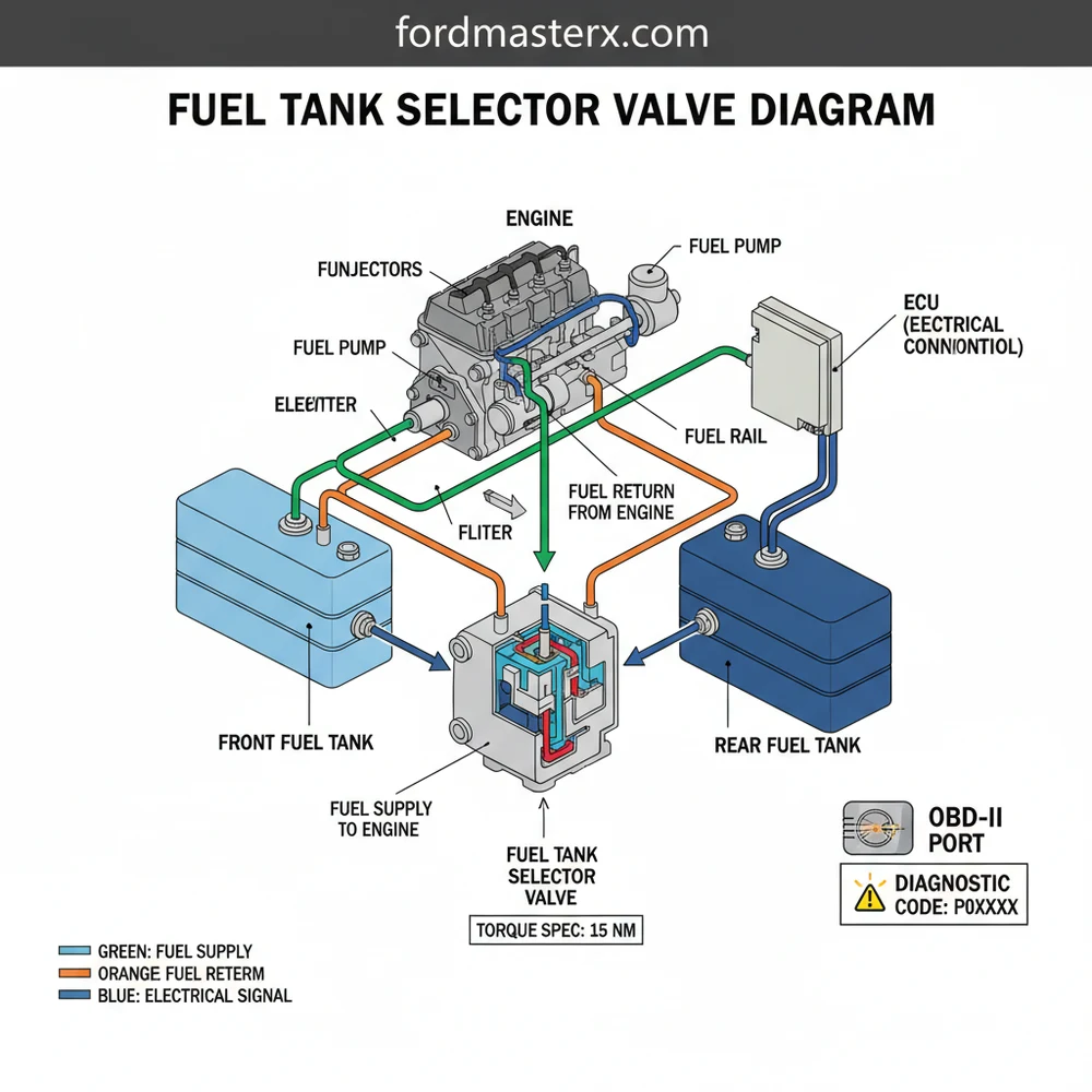
A comprehensive fuel tank selector valve diagram typically illustrates a six-port configuration, which is the industry standard for fuel-injected vehicles. These six ports are divided into two distinct functional groups: the “Supply” side and the “Return” side. On the supply side, two ports receive fuel from the primary and secondary tanks, while the third port sends that fuel toward the engine’s fuel rail. Conversely, the return side features two ports that receive unused fuel back from the engine and one port that directs it back into the currently selected tank.
The diagram also highlights the electrical connector, which usually contains four to six pins. These pins connect the valve to the vehicle’s ECU (Engine Control Unit) and the fuel gauge sender units. In many modern systems, the selector valve does not just move fuel; it also switches the electrical signal for the fuel gauge so that your dashboard correctly reflects the level of the tank currently in use. When viewing a diagram, you will notice color-coded wiring—often using red or green for power, black for ground, and various striped wires for the sender signals.
Visualizing these internal pathways is crucial because it explains how “cross-flow” occurs. Cross-flow is a common failure where fuel is pulled from one tank but returned to the other, leading to an overflow situation. By studying the internal gates shown in the diagram, you can see how a mechanical failure in the internal O-rings or the motorized shuttle prevents the valve from sealing one side completely. This level of detail is necessary for anyone attempting to troubleshoot fuel delivery issues or perform a restoration on a vintage dual-tank system.
[DIAGRAM_PLACEHOLDER: A detailed 2D technical illustration showing a 6-port fuel selector valve. Labels include: Tank 1 Supply, Tank 2 Supply, Engine Supply, Tank 1 Return, Tank 2 Return, Engine Return. An inset shows the 6-pin electrical connector with wiring labels for ECU Signal, Ground, and Fuel Sender.]
Step-by-Step Guide to Installation and Interpretation

Interpreting a fuel tank selector valve diagram and applying it to a physical repair requires a methodical approach. Before beginning, ensure you have the necessary tools: a set of line disconnect tools, a basic socket set, a digital multimeter, and safety gear. Because you are working with pressurized fuel, safety must be your absolute priority.
Fuel systems are under high pressure. Always relieve the fuel system pressure by removing the fuel pump fuse and cranking the engine until it stalls before disconnecting any lines.
- ✓ Step 1: Identify the Lines: Use the diagram to label each fuel line before removal. Use masking tape to mark “Main Supply,” “Aux Supply,” “Main Return,” and “Aux Return.”
- ✓ Step 2: Disconnect Power: Disconnect the negative battery terminal. This prevents accidental sparks and protects the ECU from electrical surges while you handle the selector valve connector.
- ✓ Step 3: Remove the Old Valve: Unscrew the mounting bolts holding the valve to the frame rail. Use your line disconnect tools to release the quick-connect fittings. Be prepared for a small amount of fuel drainage.
- ✓ Step 4: Inspect the Connector: Before installing the new unit, inspect the electrical harness for corrosion. Use the diagram to verify that the pin configuration on your new valve matches the vehicle’s harness.
- ✓ Step 5: Mount and Torque: Place the new valve in position. Tighten the mounting bolts to the manufacturer’s specific torque spec to ensure the unit does not vibrate loose, which could lead to line fatigue.
- ✓ Step 6: Connect Lines and Electricals: Snap the fuel lines onto the corresponding ports as indicated by your diagram. Ensure you hear a “click” for each fitting. Reattach the electrical harness.
- ✓ Step 7: System Priming and Leak Check: Reinstall the fuel pump fuse and reconnect the battery. Cycle the ignition to the “On” position several times without starting the engine to prime the lines. Inspect every connection for leaks.
While you are underneath the vehicle, it is a great time to perform a general inspection. Check the condition of the lines to ensure they aren’t near the exhaust or obstructing the coolant flow to the rear heater cores (if equipped). Also, take a moment to look at the front of the engine; while unrelated to the fuel valve, checking the accessory belt for cracks or the timing chain cover for leaks is part of a healthy maintenance routine.
Common Issues and Troubleshooting

When a fuel tank selector valve fails, it often triggers a check engine light on your dashboard. Using an OBD-II scanner is the most efficient way to begin your diagnosis. Look for a specific diagnostic code related to fuel level sensors or fuel trim lean/rich conditions. If the valve is stuck between positions, the engine may starve for fuel, or the fuel gauge may read empty despite having a full tank.
The diagram is your best friend during troubleshooting. If you suspect an electrical failure, use the diagram to identify the power and ground pins. With the ignition on, have an assistant toggle the tank switch while you check for voltage at the connector. If voltage is present but the valve does not click or move, the internal solenoid has likely failed. If there is no voltage, the issue lies in the dash switch or the wiring harness. Another frequent issue is “sediment jamming,” where debris from an old steel tank enters the valve and prevents the internal gate from sliding. This often results in the valve getting stuck on one tank permanently.
Tips and Best Practices for Longevity
To ensure your fuel tank selector valve lasts for the life of the vehicle, regular maintenance of the entire fuel system is required. One of the most effective pro tips is to never let both tanks run extremely low simultaneously. Running on “empty” draws concentrated sediment from the bottom of the tank into the selector valve, which can score the internal seals and lead to internal leaking.
When replacing the valve, always install a fresh fuel filter at the same time. This prevents any debris disturbed during the repair from reaching your fuel injectors or the new valve’s delicate internals.
If you are performing this repair on an older vehicle, consider upgrading to high-quality nylon or stainless steel braided lines if the original rubber lines show signs of dry rot. When securing the valve, ensure the wiring harness is tucked away from moving parts. A harness that rubs against a rotating component or an accessory belt will eventually short out, potentially damaging the ECU.
Finally, always use high-quality, OEM-spec replacement valves. While “universal” valves are cheaper, they often lack the correct internal porting for return-style fuel systems, which can lead to improper fuel pressure regulation. By following your fuel tank selector valve diagram closely and adhering to these best practices, you can ensure a reliable fuel system that performs perfectly under any load or driving condition. Utilizing your OBD-II tool periodically to check for pending codes can also catch a failing valve before it leaves you stranded on the side of the road.
Frequently Asked Questions
Where is the fuel tank selector valve located?
The selector valve is typically located on the inner frame rail between the two fuel tanks. On many older trucks, it sits near the driver-side rail. You can find it by following the fuel lines from either tank toward the engine until they converge at a single motorized block.
What does fuel tank selector valve diagram show?
The diagram shows the 6-port configuration for fuel supply and return lines, along with the electrical connector pinout. It identifies which wires control the internal motor and which ones send fuel level signals to the dashboard gauge, allowing for precise electrical testing with a multimeter or test light.
How many wires and connections does the valve have?
A standard motorized valve usually features a 5-pin or 6-pin electrical connector and six hose ports. Two ports connect to the front tank, two to the rear tank, and two lead to the engine. The wiring includes power, ground, and signal wires for the fuel level sending units.
What are the symptoms of a bad fuel tank selector valve?
Common symptoms include the engine stalling when switching tanks or the fuel gauge showing ‘Empty’ despite having fuel. A failure can trigger a check engine light if it causes a lean condition. Technicians use an OBD-II scanner to look for a diagnostic code related to fuel trim or level sensor errors.
Can I replace the fuel tank selector valve myself?
Yes, this is a common DIY task for those comfortable working around fuel. It involves disconnecting fuel lines and an electrical plug. However, you must relieve fuel system pressure first and have containers ready to catch spills. If the OBD-II system shows complex electrical faults, professional diagnosis is recommended.
What tools do I need for this task?
You will need a basic socket set, fuel line disconnect tools, and a multimeter for electrical testing. When reinstalling, ensure you follow the specific torque spec for the mounting bracket bolts to prevent vibration. Use a scan tool to clear any diagnostic code that may have been stored in the ECU.