Ford Upfitter Switches Wiring Diagram: Easy Setup Guide
A Ford upfitter switches wiring diagram maps the factory-installed auxiliary toggle switches to their corresponding hot wire pigtails, typically located under the hood or behind the passenger kick panel. To complete an installation, you must connect your accessory to the specific switch wire and provide a dedicated ground wire for each circuit.
📌 Key Takeaways
- Identifies the specific color-coded wires for each auxiliary toggle switch
- The relay box is the most important component to locate for power distribution
- Always match the accessory amperage draw to the switch’s specific fuse rating
- Use heat-shrink butt connectors to prevent corrosion at the pigtail connections
- Essential when adding light bars, winches, or air compressors to a Ford truck
Whether you are outfitting your Ford truck for off-road adventures, heavy-duty work, or emergency response, the factory-installed auxiliary system is one of the most versatile tools at your disposal. Accessing this power requires a clear understanding of the ford upfitter switches wiring diagram to ensure that your aftermarket accessories function safely and reliably. This guide is designed to help you navigate the complex web of color-coded wires, relay boxes, and pass-through circuits. By following the precise wiring sequence and terminal identification provided here, you will be able to bridge the gap between your cab switches and your external equipment without compromising your vehicle’s electrical integrity.
The Ford upfitter system consists of two main parts: the overhead or dash-mounted switches and the auxiliary relay box located in the engine compartment. The diagram connects these two via a set of pass-through wires that eliminate the need to drill through the firewall.
Decoding the Ford Upfitter Switches Wiring Diagram
The central component of any Ford auxiliary setup is the Upfitter Interface Module (UIM) and its associated relay block. When you look at a ford upfitter switches wiring diagram, you are looking at a roadmap that describes how low-current signals from your fingers travel to high-current outputs under the hood. Most modern Ford trucks feature six switches, numbered Aux 1 through Aux 6. These switches do not power your accessories directly; instead, they trigger relays that pull high-amperage current from the battery.
The diagram identifies specific voltage ratings for each circuit. Typically, switches 1 through 4 are rated for lower amperage (around 25 amps), while switches 5 and 6 are high-capacity circuits (often 40 to 70 amps) designed for heavy loads like winches or large light bars. The diagram also highlights the “pass-through” wires. These are blunt-cut wires found near the passenger-side footwell and corresponding wires near the battery or firewall. These act as a bridge, or a traveler wire system, allowing you to move the signal from the interior to the exterior seamlessly.
Each switch is associated with a specific color code. For instance, Aux 1 might be Brown with a Green stripe, while Aux 6 might be Violet with an Orange stripe. It is vital to consult the specific diagram for your vehicle’s trim, as Ford occasionally shifts these colors between the F-150 and the Super Duty lines. The diagram also illustrates the common terminal points where multiple accessories might share a ground or a power source, though independent grounding is always recommended for high-draw items.
——————————————————-
| [RELAY 1: 25A] | [RELAY 2: 25A] | [RELAY 3: 25A] |
| Wire: BRN/GRN | Wire: VIO/ORG | Wire: BLU/GRN |
——————————————————-
| [RELAY 4: 25A] | [RELAY 5: 40A] | [RELAY 6: 40A] |
| Wire: GRY/BRN | Wire: BRN/WHT | Wire: VIO/BRN |
——————————————————-
| PASS-THROUGH BUNDLE (Blunt Cut) |
| (Located near firewall/Battery) |
——————————————————-
Note: Colors vary by chassis type. Always verify with a multimeter.
Step-by-Step Installation and Wiring Guide
Reading a ford upfitter switches wiring diagram is the first step, but physical implementation requires a systematic approach. Follow these steps to ensure a professional-grade installation.
Step 1: Locate the Customer Access Wires
Open your hood and look for a bundle of blunt-cut wires wrapped in tape near the battery or the driver-side firewall. Inside the cabin, you will find a matching set of wires tucked behind the kick panel or under the glovebox. These are your “travelers” that connect the inside to the outside.
Step 2: Identify Your Switch Circuit
Using your diagram, determine which switch you want to use for your accessory. If you are installing a high-draw air compressor, you must use Switch 5 or 6 due to their higher amperage capacity. Identify the hot wire color for that specific switch in the engine bay bundle.
Step 3: Prepare the Grounding Point
Every circuit needs a return path. Identify a factory grounding stud on the chassis. While some systems use a neutral wire in AC applications, in your Ford’s DC system, the ground wire (typically black or green) must be securely fastened to the vehicle frame or a dedicated grounding block. Ensure the surface is free of paint for maximum conductivity.
Step 4: Connect the Accessory to the Relay Output
Strip the end of the hot wire (the color-coded wire from the relay box) and connect it to the positive lead of your accessory. Use a high-quality crimp connector or solder the joint. If you are using an external distribution block, you may find a brass screw terminal to secure the connection; ensure it is tightened to the correct torque to prevent arcing.
Step 5: Select the Correct Wire Gauge
Do not overlook the gauge of the wire you are adding. If the factory upfitter wire is 12-gauge, your extension to the accessory should be at least 12-gauge or thicker (lower number). Using a wire that is too thin for the voltage and amperage will cause heat buildup and potential fire hazards.
Step 6: Verify the Fuse Ratings
Before flipping the switch, check the auxiliary fuse box (usually located under the hood). Ensure the fuse matches the requirement of your accessory and the limit of the switch. Never replace a 25A fuse with a 40A fuse just to stop it from blowing; this indicates a short or an overloaded circuit.
Step 7: Final Testing
Turn the ignition to the “On” or “Accessory” position. Flip your chosen upfitter switch. The indicator light on the switch should illuminate, and your accessory should receive power. Use a multimeter to check the voltage at the accessory terminal to ensure there isn’t a significant drop across the length of the wire.
Never tap directly into the switch wires inside the cabin to power a high-amperage device. The interior wires are only meant to signal the relays. Drawing heavy current through the dash can melt the wiring harness and damage the vehicle’s computer systems.
Common Issues & Troubleshooting

Even with a perfect ford upfitter switches wiring diagram, you may encounter issues during the installation or after a few months of use. One of the most common problems is the accessory failing to turn on despite the switch light being active. This usually points to a failure in the pass-through connection or a poor ground wire contact.
Another frequent issue is the “phantom load,” where an accessory works intermittently. This is often caused by using an incorrect gauge of wire that creates too much resistance, or a loose common terminal connection where multiple wires meet. If you find a brass screw terminal that looks discolored or melted, it is a sign of high resistance and heat, requiring immediate replacement.
If a switch refuses to light up at all, check the primary “Upfitter Relay” fuse. This fuse powers the entire logic of the system. If this is intact but the switches are dead, the issue may lie within the Upfitter Interface Module itself, which may require a professional diagnostic tool to reset.
Always use marine-grade heat shrink tubing over your connections. Engine bays are harsh environments filled with moisture and salt, which can quickly corrode an exposed hot wire or terminal, leading to circuit failure.
Tips & Best Practices for Wiring Success
To get the most out of your Ford’s auxiliary system, think of the ford upfitter switches wiring diagram as a living document. Mark down which accessories you have connected to which colors and keep this note in your glovebox. This makes future troubleshooting significantly easier for you or a future technician.
When routing your wires, follow the path of the existing factory looms. This protects your wires from moving parts like steering columns or hot components like exhaust manifolds. Use plenty of zip ties to secure the traveler wire bundle so it doesn’t chafe against the sharp edges of the firewall.
- ✓ Use a Multimeter: Always test for 12V voltage at the blunt-cut ends before making permanent connections.
- ✓ Label Everything: Use a label maker to identify the “Aux 1,” “Aux 2,” etc., on the wires in the engine bay.
- ✓ Quality Parts: Choose copper lugs and high-quality relays if you are expanding the system beyond the factory six switches.
- ✓ Dielectric Grease: Apply a small amount to any brass screw or exposed terminal to prevent oxidation.
By respecting the amperage limits and color codes defined in the ford upfitter switches wiring diagram, you ensure that your truck remains as reliable as the day it left the factory. Whether you are connecting a simple light or a complex hydraulic pump, the key is clean connections, proper grounding, and the right wire gauge for the job. Safe wiring!
Frequently Asked Questions
Where is the upfitter switch wiring located?
The blunt-cut pigtails for Ford upfitter switches are usually found in one of two places: under the hood near the driver-side firewall fuse box, or tucked behind the passenger-side kick panel. Consult your vehicle’s owner manual to confirm the exact location for your specific model year and trim.
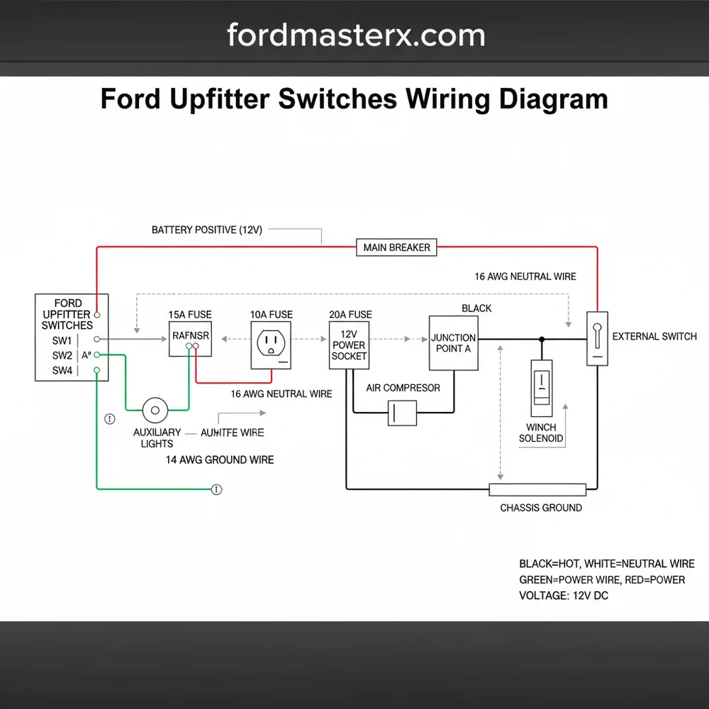
What does the upfitter switches wiring diagram show?
This ford upfitter switches wiring diagram provides a visual map of the electrical path from the cab switches to the relay box. It highlights which color wire corresponds to each switch, ensuring you tap into the correct hot wire to provide power to your aftermarket accessories safely.
How many wires does the upfitter switch system have?
Most Ford systems feature four to six individual hot wire leads, each color-coded. These wires connect through a common terminal inside the relay box. While the factory provides the power lead, you are responsible for providing a ground wire and occasionally a neutral wire path for complex components.
What are the symptoms of a bad upfitter switch connection?
Symptoms include an accessory failing to power on, intermittent operation, or a switch that won’t light up. Use a multimeter to test for voltage at the hot wire. If power is present but the device fails, check for a loose ground wire or a blown fuse in the box.
Can I install these switches myself?
Yes, if your truck didn’t come with them, OEM upfitter switch kits are available. Installation involves mounting the overhead or dash switch bank and routing the harness to the engine bay. It is a manageable DIY project for anyone comfortable with basic automotive electrical systems and circuit diagrams.
What tools do I need for upfitter switch wiring?
You will need a multimeter or test light to verify power, wire strippers, and a quality crimping tool. Since these connections are often exposed to the elements, using marine-grade heat-shrink connectors is highly recommended to protect the hot wire and ground wire from moisture and salt.


