Ford Upfitter Switches Wiring Diagram: Easy Setup Guide
The Ford upfitter switches wiring diagram shows how to connect accessories to the factory relay box. Unlike home circuits using a neutral wire or traveler wire, this system uses a chassis ground wire and a fused hot wire. Simply connect your device to the relay’s common terminal output for reliable power.
📌 Key Takeaways
- Simplifies the integration of high-draw accessories like winches or light bars
- Uses factory-installed relays to protect the primary electrical system
- Requires matching accessory amperage to the specific switch fuse rating
- Utilizes color-coded blunt-cut wires for easy identification
- Essential for maintaining a clean, professional look in truck modifications
If you are looking to integrate high-powered accessories into your truck, understanding the 2023 ford upfitter switches wiring diagram is the first step toward a professional and safe installation. Ford’s factory-installed auxiliary switches provide a clean, integrated way to control everything from LED light bars to winches without drilling into your dashboard. However, the complexity of the modern electrical system means you must know exactly where the blunt-cut wires are located, how to identify each switch by its specific color code, and the maximum amperage each circuit can handle. This guide will walk you through the entire wiring process, ensuring your project meets factory standards for reliability and performance.

Understanding the 2023 Ford Upfitter Switches Wiring Diagram
The 2023 ford upfitter switches wiring diagram is designed to help users identify the connection points between the overhead console switches and the auxiliary relay box located in the engine compartment. Unlike traditional aftermarket setups where you must run your own relays and fuses, Ford has pre-wired these components for you. The system consists of six switches, each linked to a specific relay and a set of “blunt-cut” wires found under the hood.
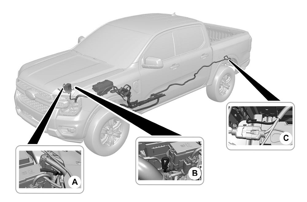
The diagram identifies several key zones. First, there is the overhead switch assembly, which sends a low-voltage signal to the relay box. Second, the High Current Central Junction Box (located near the passenger side battery) houses the fuses and relays. Third, the output wires—the actual power sources for your accessories—are usually tucked away near the driver’s side firewall or next to the fuse box.
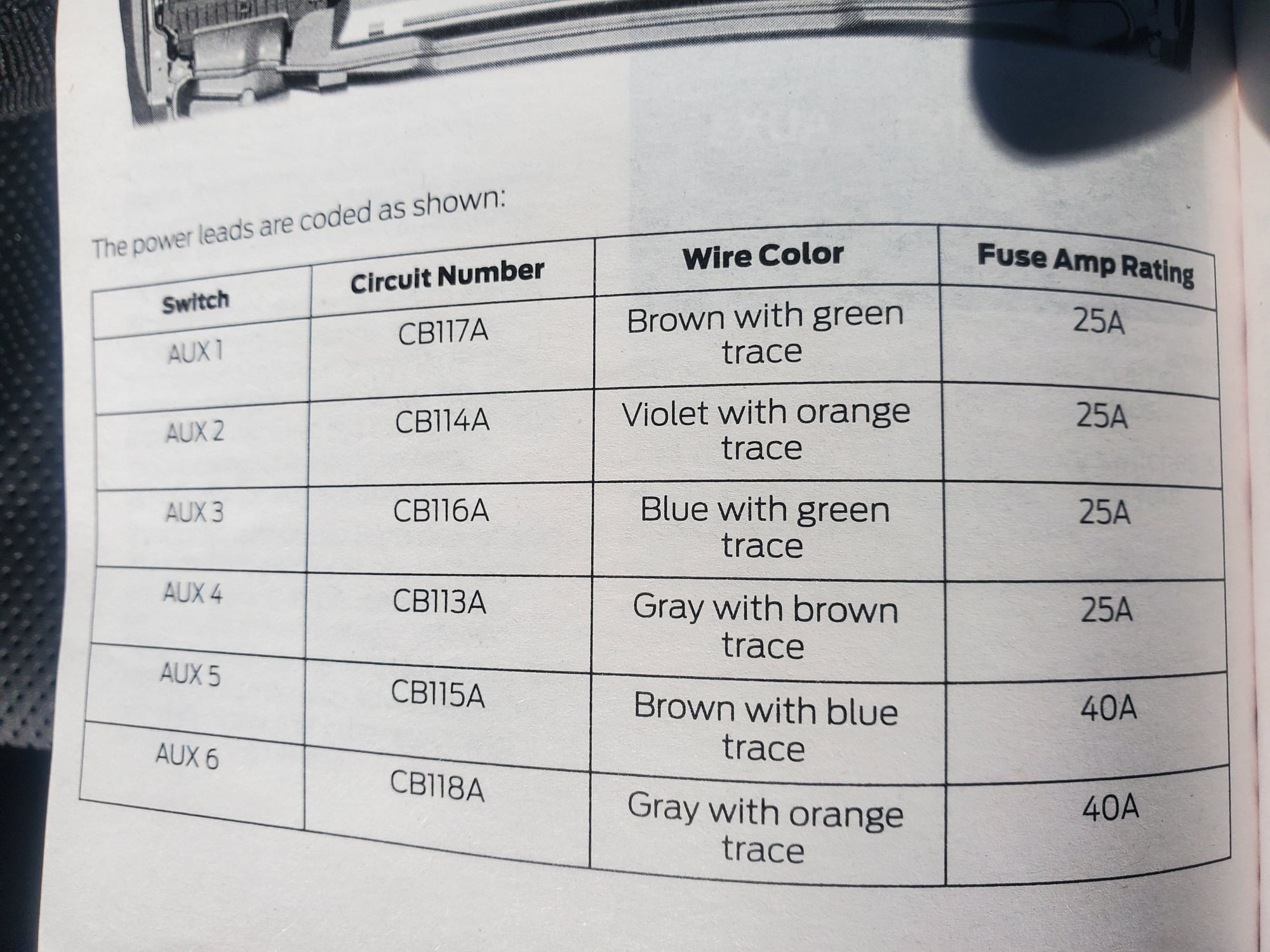
A critical aspect of the diagram is the color-coding scheme. Each switch corresponds to a specific wire color. For instance, Switch 1 typically uses a Brown/Green wire, while Switch 6 uses a Green/Orange wire. The diagram also distinguishes between the power output wires and the “pass-through” wires. Pass-through wires are extra, non-powered wires that run from the cabin to the engine bay, allowing you to “travel” signals back and forth for specialized equipment. Identifying the common terminal for your ground wire is equally important, as every accessory requires a solid path back to the battery or chassis to complete the circuit and maintain stable voltage.
For the 2023 model year, Switches 1 through 4 are rated at 25 Amps each. Switches 5 and 6 are high-capacity circuits, rated at 40 Amps each. Never exceed these ratings, or you risk blowing the internal fuses or damaging the relay box.
Step-by-Step Guide to Installation and Interpretation
Navigating the 2023 ford upfitter switches wiring diagram requires a systematic approach. Follow these steps to ensure your wiring is secure and functional.
Step 1: Locate the Auxiliary Wire Bundles
The first challenge is finding the wires. In most 2023 configurations, you will find two sets of blunt-cut wires. The main power output bundle is usually located in the engine compartment, often near the firewall on the driver’s side or clipped to the side of the battery box. These are the wires that receive 12V power when the switches are flipped. The second bundle is the pass-through set, which allows you to move signals from the interior to the exterior without drilling holes.
Step 2: Identify the Color-Coded Hot Wire
Using the wiring diagram, identify the hot wire for the specific switch you wish to use. If you are installing a high-draw item like a compressor, you should choose Switch 5 or 6. For a 40A circuit (Switch 5), look for the Brown/White wire. For a 25A circuit (Switch 1), locate the Brown/Green wire. Strip a small portion of the insulation back to prepare for the connection.
Step 3: Establish a Solid Ground Connection
Every electrical accessory needs a ground wire. Do not attempt to ground your accessory back to the upfitter wire bundle; instead, find a factory ground stud on the chassis or connect directly to the negative terminal of the battery. Using a brass screw or a dedicated ground terminal ensures that there is no resistance, which prevents flickering and heat buildup.
Step 4: Select the Correct Wire Gauge
The gauge of the wire you use to extend the factory pigtail to your accessory is vital. For the 40-amp switches, you should use at least 10-gauge or 8-gauge wire depending on the distance. For the 25-amp switches, 12-gauge or 14-gauge is typically sufficient. Using a wire that is too thin will cause a drop in voltage and can lead to a fire hazard.
Step 5: Connect the Traveler Wire (If Necessary)
If your accessory requires a trigger signal inside the cab (such as a controller for a snowplow), you will need to utilize the traveler wire system. Connect your signal wire to one of the pass-through wires in the engine bay, then find the matching color-coded wire under the dashboard (usually near the passenger footwell or steering column). This creates a continuous path without needing to pierce the firewall.
Step 6: Secure Connections and Test
Use heat-shrink butt connectors to join your accessory’s hot wire to the upfitter hot wire. Standard electrical tape is not recommended for automotive engine bays due to heat and moisture. Once connected, turn the ignition to the “On” or “Accessory” position, flip the overhead switch, and use a multimeter to verify that you are receiving the correct voltage at the accessory.
Always disconnect the negative battery cable before working on the electrical system. A short circuit during installation can fry sensitive electronic control modules (ECMs) or cause the upfitter relays to fail prematurely.
Common Issues and Troubleshooting
Even with a detailed 2023 ford upfitter switches wiring diagram, you may encounter obstacles during the installation process.
One of the most frequent problems is the switch not providing power despite being flipped “on.” This is often due to the fact that the upfitter switches are typically ignition-hot, meaning they will not function unless the key is in the accessory or run position. If there is still no power, check the auxiliary fuse box. Each switch has a dedicated fuse; if a 25A switch was accidentally loaded with a 40A accessory, the fuse will pop instantly to protect the system.
Another common issue involves poor grounding. If your light bar is dim or your winch is stuttering, the ground wire likely has a weak connection. Ensure the common terminal is free of paint and rust. If you are using an aftermarket bus bar, check that the brass screw connections are tight and not corroded. Voltage drop is another symptom of using the wrong gauge wire for long runs. Always measure the voltage at the source and then at the accessory to ensure they match.
Tips and Best Practices for a Clean Install
To get the most out of your upfitter system, follow these professional recommendations:
- ✓ Label Your Wires: Use a label maker to mark each wire near the relay box. This makes future troubleshooting much faster if you add more accessories later.
- ✓ Use Wire Loom: Protect your new wiring with split-conduit wire loom. This prevents the insulation from rubbing against sharp metal edges in the engine bay.
- ✓ Dielectric Grease: Apply a small amount of dielectric grease to your terminal connections to prevent oxidation, especially if you live in a region where road salt is used.
If you need more than 40 Amps for a heavy-duty winch, do not bridge two upfitter switches together. Instead, use an upfitter switch to trigger a larger, external 80A or 100A relay connected directly to the battery. This keeps the factory wiring safe while still giving you switch control.
Maintenance of your upfitter system is relatively simple. Every six months, inspect the relay box for any signs of moisture or heat damage. Ensure that the wires haven’t vibrated loose from their connectors. If you notice a switch feels “mushy” or doesn’t click, the overhead console unit may need cleaning or replacement, though this is rare in newer models.
By strictly following the 2023 ford upfitter switches wiring diagram and adhering to proper electrical standards regarding gauge and voltage, you can turn your truck into a highly functional tool. Whether you are running work lights or emergency equipment, the factory upfitter system is the most reliable way to power your gear without compromising your vehicle’s warranty or electrical integrity. Always remember to prioritize safety by using fuses and high-quality connectors throughout your installation.
Frequently Asked Questions
Where is the upfitter relay box located?
In most Ford trucks, the upfitter relay box is located in the engine compartment, usually near the driver-side firewall or battery. The blunt-cut wires for connecting accessories are typically found bundled nearby or behind the passenger-side kick panel, depending on your specific vehicle trim and model year.
What does the upfitter diagram show?
The diagram illustrates the electrical path from the overhead switch console to the relay junction box. It details how the internal circuitry triggers high-current outputs, allowing you to power heavy-duty equipment without running wires through the firewall or overloading the standard fuse panels in your vehicle.
How many connections does the upfitter system have?
The standard system features six switches, each corresponding to a dedicated hot wire output. You must connect your accessory to one of these outputs and provide a solid ground wire connection to the chassis. These circuits are independent and designed to handle varying amperage levels for different needs.
What are the symptoms of a bad upfitter switch?
Symptoms of a failing switch or relay include an accessory that won’t turn on, blown fuses, or the switch indicator light failing to illuminate. If you hear a clicking sound but no power reaches the device, the issue is likely a loose common terminal or a damaged relay.
Can I install these switches myself?
If your Ford truck is pre-wired for upfitters, adding accessories is a simple DIY project. However, retrofitting the entire switch console and relay box into a truck not originally equipped with the package is a complex task involving extensive harness routing and potential PCM programming to function correctly.
What tools do I need for installation?
You will need a basic automotive electrical kit, including wire strippers, high-quality crimpers, and a digital multimeter for testing circuits. Heat-shrink tubing and electrical tape are necessary for weatherproofing connections, while zip ties help secure the wiring away from heat sources or moving engine components.


