Ford Throttle Position Sensor Diagram: Easy Setup Guide
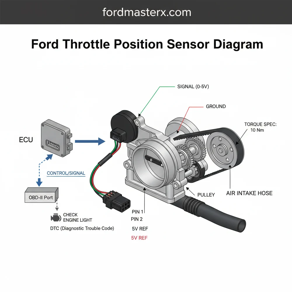
The Ford throttle position sensor (TPS) diagram details the three-wire connection between the sensor and the ECU. It typically identifies the 5-volt reference wire, the signal return, and the ground wire. This guide helps you identify the correct pin configuration to ensure accurate throttle angle data reaches the vehicle computer.
📌 Key Takeaways
- Main purpose of this diagram is mapping electrical connections between the TPS and the ECU.
- The most important component to identify is the 5-volt reference signal wire for proper voltage.
- Always disconnect the vehicle battery before testing sensitive electronic circuits to prevent short circuits.
- Use a digital multimeter to verify diagram pinouts against actual sensor output during testing.
- Consult this diagram when diagnosing a check engine light or persistent engine stalling issues.
When you are facing a stumbling engine, poor fuel economy, or a hesitant throttle response in your Ford vehicle, having an accurate ford throttle position sensor diagram is the most critical tool in your diagnostic arsenal. Locating this small but vital component can be the difference between a quick twenty-minute fix and hours of frustrated searching under the hood. A precise diagram does more than just show a part; it provides the spatial context needed to navigate the crowded engine bay, identifying how the sensor interfaces with the throttle body and the vehicle’s computer system. This guide will walk you through the exact location of the TPS, how to interpret its wiring, and the steps required to ensure your engine returns to peak performance.
The Ford throttle position sensor (TPS) is typically a small, plastic-housed component mounted directly to the side of the throttle body assembly. In a standard ford throttle position sensor diagram, you will see the sensor positioned on the end of the throttle plate shaft. This allows the sensor to rotate in perfect synchronization with the physical movement of the butterfly valve inside the intake. For most Ford engines, the diagram highlights a three-wire configuration: a 5-volt reference signal from the ECU, a ground wire, and a signal return wire that tells the computer exactly how far the throttle is open.
On older Ford models with a cable-driven throttle, the TPS is a standalone unit. On newer “Drive-by-Wire” systems, the function may be integrated into the Electronic Throttle Control (ETC) motor assembly, though the diagnostic principles remain largely the same.
Visual landmarks are essential for finding the sensor quickly. When looking at the engine from the front of the vehicle, follow the large plastic or rubber air intake tube from the air filter box toward the engine. This tube connects directly to the throttle body. The TPS is almost always mounted on the side of this metal housing, opposite the throttle linkage or integrated into the side of the electronic actuator. In some V6 or V8 configurations, the sensor may be tucked slightly under the upper intake manifold or near the coolant flow bypass hoses, making the diagram indispensable for identifying the correct electrical connector.
To successfully use a ford throttle position sensor diagram for repair or testing, you must follow a logical sequence of identification and verification. Understanding the layout is the first step toward a professional-grade repair.
- ✓ Identify the Intake Path: Begin by locating the air cleaner assembly and following the ducting to the aluminum throttle body housing.
- ✓ Locate the Sensor Body: Look for a black plastic component secured by two small screws (usually Phillips or Torx head) on the side of the throttle body.
- ✓ Map the Wiring: Match the colors of the wires on your vehicle to those listed in your specific ford throttle position sensor diagram to identify the signal, power, and ground.
- ✓ Check for Obstructions: Note the proximity of the accessory belt or the cooling fans, ensuring you have a clear path to reach the sensor without damaging surrounding components.
- ✓ Clear the Area: If the sensor is obscured by the coolant flow reservoir or air intake piping, carefully remove these items after the engine has cooled completely.
Before beginning any work, gather a basic toolkit including a digital multimeter, a set of Torx bits or screwdrivers, and an OBD-II scanner. Safety is paramount; ensure the vehicle is in park with the emergency brake engaged. If you are working near the front of the engine, be mindful of the accessory belt and ensure no loose clothing can get caught in the pulleys.
Never attempt to adjust or remove the TPS while the engine is running. Disconnect the negative battery terminal before disconnecting any ECU components to prevent electrical surges or accidental shorting.
Once you have identified the sensor using the ford throttle position sensor diagram, the replacement process involves removing the electrical connector by depressing the plastic locking tab. Carefully unscrew the mounting fasteners. When installing the new sensor, many Ford models require you to “clock” the sensor—meaning you place it onto the shaft and rotate it slightly to line up the bolt holes. This pre-loads the internal spring. Once seated, tighten the screws to the specific torque spec, which is usually quite low (around 10-20 inch-pounds). Over-tightening can crack the plastic housing, leading to immediate sensor failure.
The primary role of the TPS is to provide constant data to the ECU. When this data becomes “noisy” or drops out entirely, the vehicle’s computer cannot accurately calculate the air-fuel ratio. This often triggers a check engine light and records a specific diagnostic code such as P0121 (Range/Performance) or P0122 (Circuit Low). Using a ford throttle position sensor diagram helps you pinpoint if the issue is the sensor itself or a break in the wiring harness.
Common symptoms of a failing TPS include:
- – Sudden surging or stalling while idling.
- – Hesitation when pressing the gas pedal.
- – Unpredictable automatic transmission shifting.
- – A significant drop in fuel economy.
If you see these signs, use your OBD-II scanner to monitor the “Absolute Throttle Position” data stream. As you slowly press the accelerator (with the engine off but the key in the “On” position), the percentage should rise smoothly from roughly 10% to 90% without any sudden jumps or drops to zero. If the data is erratic, the diagram will guide you in testing the 5-volt reference wire to ensure the ECU is actually sending power to the sensor.
Before replacing the sensor, clean the throttle body bore with a specialized throttle body cleaner. Carbon buildup can cause the butterfly valve to stick, mimicking the symptoms of a bad TPS and leading to unnecessary parts replacement.
When performing maintenance, it is also wise to inspect the surrounding areas mentioned in comprehensive ford throttle position sensor diagrams. For instance, check the condition of the vacuum lines and the proximity of the timing chain cover for any oil leaks that might contaminate the electrical connector. Oil or coolant flow from a leaking bypass hose can seep into the TPS housing, causing internal corrosion and signal failure.
To save costs, always verify the wiring harness before buying a new sensor. Wires can become brittle due to engine heat, especially those running near the exhaust manifold or tucked behind the accessory belt. A simple continuity test between the TPS connector and the ECU pins can save you the price of a new part. If you do need a replacement, opt for an Original Equipment Manufacturer (OEM) part. Ford sensors are calibrated to specific resistance ranges that some aftermarket “universal” sensors may not perfectly match, leading to a lingering check engine light even after the repair.
Finally, once the new sensor is installed and the ford throttle position sensor diagram has helped you confirm all connections are secure, you may need to perform a “Throttle Relearn” procedure. This usually involves letting the engine idle for several minutes followed by a period of driving at various speeds, allowing the ECU to map the new idle and wide-open throttle voltages. By following these steps and utilizing a detailed diagram, you ensure that your Ford remains reliable, efficient, and responsive to your every command on the road. High-quality maintenance starts with high-quality information, and knowing exactly where and how your throttle position sensor functions is the key to automotive DIY success.
Step-by-Step Guide to Understanding the Ford Throttle Position Sensor Diagram: Easy Setup Guide
Identify the TPS location on the throttle body using the diagram reference.
Locate the three-pin connector and inspect for any visible corrosion or damage.
Understand how the 5-volt reference signal interacts with the ECU during operation.
Apply the multimeter probes to the signal wire to test for smooth voltage changes.
Verify that the sensor is secured to the manufacturer’s specific torque spec.
Complete the process by clearing the check engine light with a diagnostic scanner.
Frequently Asked Questions
Where is the Ford throttle position sensor located?
The Ford TPS is typically located on the side of the throttle body assembly, bolted directly to the butterfly valve shaft. It monitors how far the throttle plate opens. You can find it by following the air intake tube to where it meets the metal engine intake manifold.
What does a Ford throttle position sensor diagram show?
This diagram shows the specific pinout assignments for the TPS connector. It illustrates the 5V power source from the ECU, the variable signal output wire, and the ground circuit. Understanding this layout is essential for performing electrical tests or replacing a damaged wiring pigtail on your Ford vehicle.
How many wires does the Ford TPS have?
Most Ford TPS units feature a three-wire configuration. One wire carries a constant 5-volt reference signal from the ECU, the second is a dedicated signal ground, and the third sends a varying voltage back to the computer based on the physical position of the throttle plate butterfly valve.
What are the symptoms of a bad Ford TPS?
Common symptoms include a persistent check engine light, sudden engine hesitating, or poor fuel economy. You might also notice a specific diagnostic code like P0121 or P0122 stored in the OBD-II system. In severe cases, the vehicle may enter a limp mode to protect the engine components.
Can I replace a Ford TPS myself?
Yes, replacing a Ford TPS is a straightforward DIY task. Once you identify the correct wiring using a diagram, you simply unscrew the old sensor and install the new one. However, some newer models require a specific calibration process through the OBD-II port to sync with the ECU.
What tools do I need for TPS troubleshooting?
You will need a digital multimeter to test voltage and continuity according to the diagram. A basic socket set or screwdrivers are required to remove the mounting bolts. Additionally, an OBD-II scanner is helpful for clearing any stored diagnostic code and verifying that the repair was successful.


