Ford Single Barrel Carburetor Diagram: Complete Guide
A Ford single barrel carburetor diagram illustrates the internal components like the float, main jet, and needle valve assembly. It provides a visual roadmap for the air-fuel mixture path, assisting mechanics in adjusting the idle or performing a full rebuild on vintage Ford engines that predate modern electronic fuel injection systems.
📌 Key Takeaways
- The diagram serves as an exploded view for identifying mechanical fuel delivery parts.
- The float and needle seat are the most critical components to identify for flooding issues.
- Always handle gasoline components in a well-ventilated area away from open flames.
- Use the diagram to ensure every small gasket and spring is returned to its specific seat.
- Use this diagram when the engine suffers from poor idling or hesitation during acceleration.
Navigating the intricate mechanical world of vintage Ford engines often leads you back to the heart of the fuel system. Whether you are restoring a classic Mustang, a Falcon, or a reliable F-100 truck, having a clear ford single barrel carburetor diagram is the first step toward achieving a smooth-running engine. This diagram serves as your roadmap for identification, cleaning, and precise calibration. In this comprehensive guide, you will learn how to identify critical components, understand the relationship between mechanical parts, and apply this knowledge to troubleshoot common performance issues. By the end of this article, you will have the confidence to overhaul your carburetor and restore the fuel efficiency and throttle response your Ford was designed to deliver.
Understanding the Component Layout
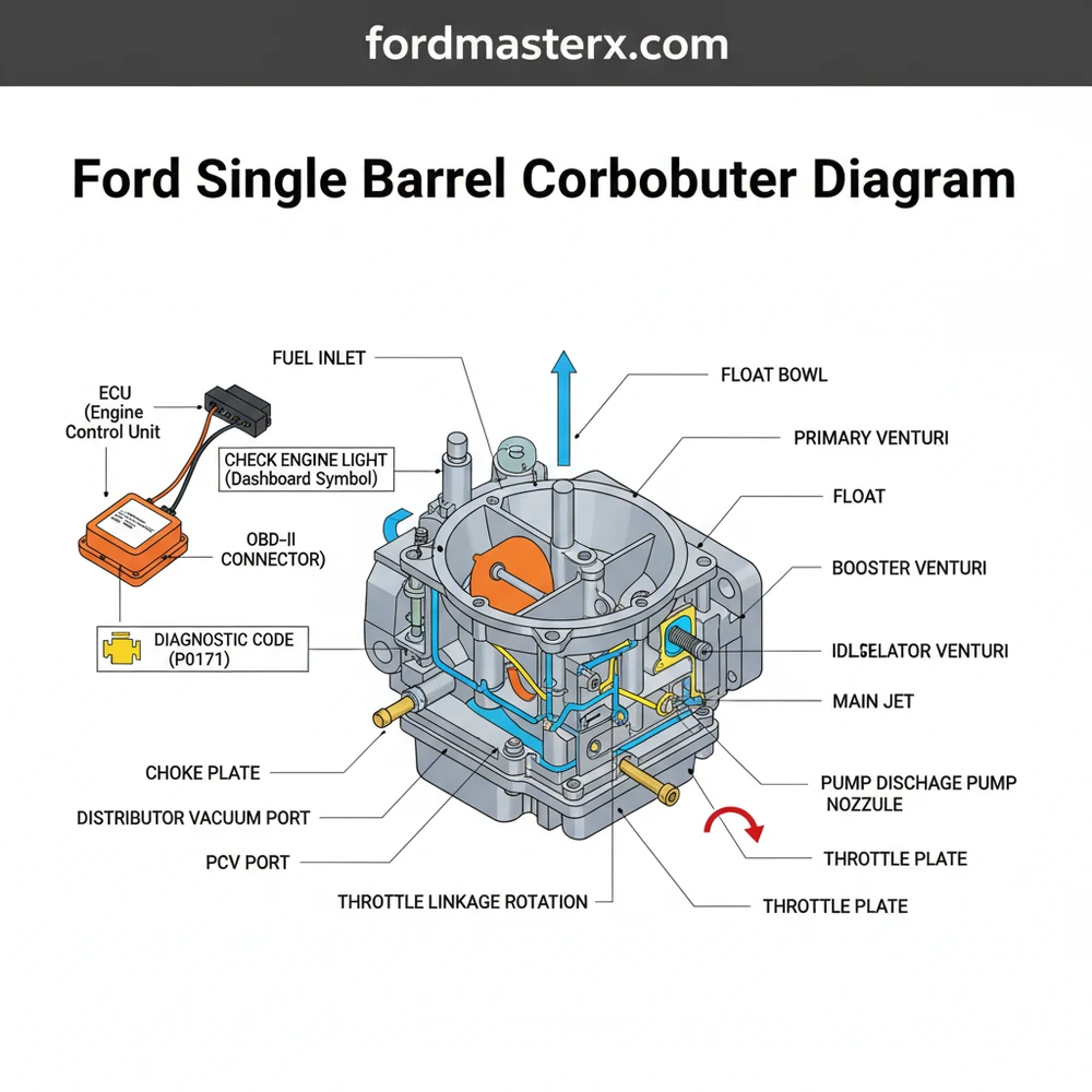
A Ford single barrel carburetor, most commonly the Autolite 1100 or the Carter YF, is a marvel of mechanical engineering that operates without the assistance of a modern ECU. The diagram for these units typically breaks down the assembly into three primary sections: the air horn (top), the main body (middle), and the throttle body (base). Each section houses specific components that must work in perfect synchronization to mix air and fuel in the correct ratio.
The air horn section is the first point of entry for atmospheric air. Here, the diagram highlights the choke plate, which restricts airflow during cold starts to enrich the mixture. You will also find the fuel inlet and the needle and seat assembly, which act as the gatekeeper for gasoline entering the unit. Moving down to the main body, the diagram identifies the float bowl—a reservoir that holds a constant supply of fuel. Within this bowl sits the float, which rises and falls with the fuel level, similar to a toilet tank mechanism. The main jet, located at the bottom of the bowl, is a precision-drilled orifice that determines how much fuel is pulled into the venturi during cruising speeds.
Most Ford single-barrel diagrams also include the accelerator pump circuit. This mechanical diaphragm “squirts” an extra shot of fuel when you press the gas pedal, preventing the engine from stumbling before the main circuit takes over.
The base, or throttle body, contains the throttle plate and the idle mixture screw. This area is critical for maintaining a steady idle. Unlike a modern vehicle where a check engine light might indicate a vacuum leak, on a single-barrel Ford, you must manually inspect the base gasket and the throttle shaft for wear. The diagram will often show the vacuum ports used for the distributor advance, ensuring that the ignition timing stays synced with the engine load.
[DIAGRAM_PLACEHOLDER: Detailed Ford Single Barrel Carburetor Exploded View showing Air Horn, Float Bowl, Accelerator Pump, and Throttle Body components with numbered labels]
Step-by-Step Guide to Reading and Using the Diagram

Interpreting a ford single barrel carburetor diagram requires a systematic approach. It is not just about looking at the parts; it is about understanding the sequence of assembly and the flow of fluids. Follow these steps to utilize your diagram effectively during a rebuild or inspection.
Step 1: Orient the Diagram to the Hardware
Before loosening a single screw, place the carburetor on a clean workbench and rotate it until it matches the orientation shown in the diagram. Identify the primary external landmarks, such as the fuel inlet, the throttle linkage, and the choke housing. This prevents confusion between the “front” and “back” of the unit, which is a common mistake for beginners.
Step 2: Identify the Circuit Path
Trace the path of fuel from the inlet through the needle and seat, into the bowl, and out through the venturi. Using the diagram to visualize this coolant flow of energy helps you understand why a blockage in one specific passage leads to a specific symptom, such as a high-speed lean condition or a rough idle.
Step 3: Document the Disassembly
As you remove components, lay them out on a magnetized tray or a numbered board that corresponds to the numbers on the diagram. Take note of the “small parts” often lost: the check balls, the tiny clips for the accelerator pump rod, and the thin gaskets. The diagram is your insurance policy; if you forget where a specific spring goes, the exploded view will show its exact anchor points.
Single barrel carburetors contain small check balls that act as one-way valves. If these are installed in the wrong order or missing entirely, the accelerator pump will fail to prime, and the car will stall upon acceleration.
Step 4: Clean and Inspect
Use the diagram to identify every “orifice” or “jet” that requires cleaning. Do not just spray the outside; use a dedicated carburetor cleaner and compressed air to blow through the passages identified in the schematic. Inspect the float—if it is brass, shake it to see if fuel is trapped inside; if it is nitrophyl (plastic), look for absorption or “heaviness.”
Step 5: Verify the Torque Spec
When reassembling the three main sections, consult your service manual for the specific torque spec. Over-tightening the screws can warp the soft cast aluminum or zinc alloy bodies, leading to permanent vacuum leaks that no amount of tuning can fix. Tighten in a “criss-cross” pattern to ensure even pressure on the gaskets.
Step 6: Setting Initial Adjustments
Before installing the carb back on the engine, use the diagram to locate the idle speed screw and the idle mixture screw. A common starting point is to gently seat the mixture screw and back it out 1.5 to 2 full turns. This provides a “base map” that allows the engine to start so you can perform fine-tuning while the engine is warm.
Step 7: Final Installation and Belt Check
Once the carburetor is bolted back to the intake manifold, check the surrounding engine components. Ensure your accessory belt is properly tensioned and that no vacuum lines are rubbing against moving parts. A well-tuned carburetor relies on a steady engine vacuum, which is also influenced by the health of your timing chain. If the chain is stretched, your vacuum readings will fluctuate, making the carburetor seem like the culprit when the issue is actually internal engine wear.
Troubleshooting Common Performance Issues

Because these vintage systems lack an OBD-II port, there is no diagnostic code to tell you what is wrong. You must be the computer. The diagram helps you isolate issues based on symptoms. For example, if the engine “floods” (too much gas), the diagram points you directly to the needle, seat, and float level. If the engine only runs with the choke partially closed, you likely have a lean condition caused by a clogged main jet or a vacuum leak at the base gasket.
- ✓ Hesitation on Acceleration: Inspect the accelerator pump diaphragm and check balls shown in the diagram.
- ✓ Hard Cold Starts: Check the choke plate tension and the heat riser tube that provides warm air to the choke housing.
- ✓ Rough Idle: Use the diagram to find the idle air bleeds; these tiny holes often get clogged with carbon deposits.
If you find that adjusting the mixture screws has no effect on the engine RPM, you are likely dealing with a massive vacuum leak or a “blown” power valve (in models that equipped them). When mechanical adjustments fail to yield results, it may be time to consult a professional who specializes in vintage fuel systems, as internal warping can sometimes occur over decades of heat cycles.
Maintenance Tips and Best Practices
To keep your Ford single barrel carburetor in peak condition, regular maintenance is mandatory. Unlike modern fuel injection which is “set and forget,” a carburetor is a living mechanical organism. Always use a high-quality fuel filter between the fuel pump and the carburetor. This prevents microscopic debris from entering the needle and seat, which is the number one cause of carburetor-related “breakdowns” on the road.
If your vehicle sits for long periods, use a fuel stabilizer. Modern ethanol-blended gasoline can turn into a varnish-like substance in as little as 30 days, clogging the precise passages shown in your diagram.
Additionally, check your spark plugs periodically. The color of the porcelain tip provides a “real-world” diagnostic of how your carburetor is performing. A tan color indicates a perfect mixture, while black/sooty indicates a rich mixture, and white/blistered indicates a lean condition. Since you don’t have a check engine light to warn you of a lean condition—which can cause engine overheating and valve damage—monitoring your plugs is your best defense.
Finally, always keep a copy of the ford single barrel carburetor diagram in your glove box or shop manual. Whether you are performing a roadside adjustment or a full winter rebuild, this visual reference is the most valuable tool in your arsenal. Understanding how each spring, screw, and gasket contributes to the venturi effect will ensure your classic Ford remains a reliable piece of automotive history for years to come.
Frequently Asked Questions
Where is the Ford single barrel carburetor located?
The carburetor is located on top of the intake manifold, directly beneath the circular air cleaner housing. It sits centrally on the engine block to distribute the air-fuel mixture to the cylinders. You must remove the air filter assembly to see the carburetor and its various linkage connections.
What does a Ford single barrel carburetor diagram show?
The diagram shows an exploded view of the entire assembly, including the throttle body, fuel bowl, float, needle and seat, and the choke mechanism. It labels every screw, gasket, and spring, showing exactly how the internal mechanical components interact to manage fuel flow and air intake without an ECU.
How many wires or connections does this carburetor have?
A standard Ford single barrel carburetor typically has very few connections. You will usually find a mechanical throttle linkage, a vacuum line for the distributor advance, and sometimes a single electric wire for an electric choke or an idle stop solenoid. It lacks the complex wiring of modern sensors.
What are the symptoms of a bad carburetor?
Symptoms include hard starting, rough idling, stalling, and poor fuel economy. Because these vehicles do not have an OBD-II port, you won’t see a check engine light or find a diagnostic code. You must rely on physical signs like black smoke or the smell of raw gasoline.
Can I rebuild this carburetor myself?
Yes, rebuilding a single barrel carburetor is a common DIY project. Unlike modern systems managed by an ECU, these are purely mechanical. With a proper diagram and a rebuild kit, you can clean the passages and replace worn gaskets to restore engine performance and smooth out the throttle response.
What tools do I need for carburetor maintenance?
You will need a set of flat-head and Phillips screwdrivers, small wrenches or a socket set, needle-nose pliers, and a can of carburetor cleaner. A wire brush and a can of compressed air are also helpful for clearing out clogged jets and internal fuel passages during the cleaning process.


