Ford Ranger Shift Linkage Diagram: Complete Layout Guide
The Ford Ranger shift linkage diagram provides a detailed layout of the mechanical structure connecting the gear selector to the transmission. By identifying each component, such as bushings and cables, you can accurately diagnose shifting difficulties, adjust the system for precision, and replace worn parts to restore smooth operation and gear alignment.
📌 Key Takeaways
- Visualizes the mechanical path from the gear shifter to the transmission
- Identifying worn bushings is critical for fixing a loose or sloppy shifter
- Always set the parking brake before inspecting the under-vehicle linkage
- Use the diagram to verify the correct cable routing and bracket placement
- Essential for troubleshooting gear engagement or indicator misalignment
When you are dealing with a gear selector that feels loose, unresponsive, or fails to engage the correct gear, a ford ranger shift linkage diagram becomes an indispensable tool for your repair process. For many owners of this iconic pickup, the shift linkage is the physical bridge between the driver’s intent and the transmission’s mechanical response. Having access to a clear schematic allows you to visualize the intricate connections that run from the steering column or center console down to the transmission housing. This article provides a comprehensive overview of the linkage system, helping you identify worn components, understand the structural layout of the assembly, and follow a systematic approach to troubleshooting and repair. Whether you are performing a routine inspection or a full replacement of the shift cable, mastering this blueprint is the first step toward restoring your vehicle’s drivability.
Anatomy of the Shift Linkage System
The Ford Ranger shift linkage system is a mechanical configuration designed to translate the movement of the gear selector into the linear motion required to move the transmission manual valve. Depending on the specific build of your vehicle, the layout may differ slightly between automatic and manual models, though the fundamental principles remains consistent. The primary component in this system is the shift cable, a heavy-duty, reinforced wire housed within a protective sheath. This cable must navigate a precise path through the engine bay and undercarriage to ensure smooth operation without binding.
The structure of the linkage typically includes several key elements: the selector lever (either on the steering column or the floor), the shift cable itself, various mounting brackets, and the transmission range sensor or manual lever at the gearbox end. A critical part of the schematic is the bushing assembly. These small, often nylon or rubber inserts sit at the eyelets where the cable connects to the levers. Over time, these bushings are prone to degradation due to heat and friction, leading to the “sloppy” shifter feel many drivers report.
In automatic transmissions, the shift linkage works in tandem with the park/neutral position switch. If your diagram shows an electrical connector near the transmission lever, it is likely the Transmission Range (TR) sensor, which tells the computer which gear is selected.
The visual breakdown of a standard Ford Ranger blueprint reveals that the system is modular. This means that if the cable snaps, you do not necessarily need to replace the entire steering column or the transmission lever. By studying the layout, you can see exactly where the cable is anchored to the vehicle’s frame or body using specialized clips and brackets. These mounting points are vital because they maintain the tension required for accurate gear selection. If a bracket becomes loose, the entire configuration loses its calibration, often resulting in a vehicle that will not start because the computer does not recognize it is in the “Park” position.
How to Read and Interpret the Schematic

Interpreting a ford ranger shift linkage diagram requires an understanding of how mechanical symbols represent physical parts. In most professional schematics, solid lines represent the primary cables, while dashed or phantom lines may indicate the range of motion or alternative configurations for different trim levels. To effectively use the diagram for a repair, follow these numbered steps to bridge the gap between the paper blueprint and the metal components in your truck.
- ✓ Step 1: Identify the Primary Anchor Points – Start by locating the two ends of the system on your diagram. One end will be the gear selector inside the cabin, and the other will be the transmission lever. This provides the “boundary” for your inspection.
- ✓ Step 2: Locate the Firewall Pass-Through – The diagram will show where the cable exits the cabin. This is a common point for the cable to rub against the chassis, making it a high-priority area for visual checks.
- ✓ Step 3: Analyze the Bushing and Eyelet Connections – Look for the circular symbols at the ends of the cable. These represent the bushings. In the diagram, these are often exploded views to show how the bushing, clip, and lever pin fit together.
- ✓ Step 4: Find the Adjustment Mechanism – Most Ford Ranger linkage systems include a plastic or metal adjustment body along the cable. The schematic will label this as the “Adjuster” or “Take-up” unit. Knowing its location is essential for fixing alignment issues.
- ✓ Step 5: Verify Hardware Requirements – Check the diagram’s legend for bolt sizes and torque specifications. This ensures that when you reassemble the structure, every component is secured to factory standards.
- ✓ Step 6: Confirm Orientation – Many diagrams provide a “Top View” and a “Side View.” Use these to ensure you aren’t installing the cable upside down or crossing it over other vital components like exhaust heat shields.
Before working on the shift linkage, always engage the parking brake and use wheel chocks. If the linkage is disconnected while the vehicle is on an incline, the transmission could slip out of Park, causing the truck to roll unexpectedly.
To perform a successful adjustment or replacement using the diagram, you will generally need a basic socket set (10mm and 13mm are common), a flathead screwdriver for prying clips, and potentially a pair of needle-nose pliers. Having a flashlight is also recommended, as the linkage often sits in shadowed areas of the transmission tunnel.
Common Issues and Troubleshooting

Even with a high-quality ford ranger shift linkage diagram, identifying the exact root of a problem requires matching symptoms to the components. The most frequent issue encountered is a “loose” shifter that moves freely without changing gears. When this occurs, the diagram helps you identify the specific bushing that has likely crumbled. If the shifter moves but the gear indicator (PRNDL) doesn’t align correctly, the problem is usually the adjustment mechanism or a stretched cable.
Another common sign of failure is the inability to remove the key from the ignition or start the engine. Ford Rangers utilize a safety interlock system that relies on the linkage being fully seated in the “Park” position. If the linkage structure is slightly out of alignment—perhaps due to a bent bracket or a worn grommet—the system will not trigger the neutral safety switch. By referencing the schematic, you can trace the path from the selector to the switch to find where the mechanical signal is being lost.
If you find that your shifter is hard to move during cold weather, the issue is often moisture trapped inside the cable sleeve that has frozen or caused internal corrosion. Replacing the cable assembly is usually the only permanent fix.
If you notice that the lever feels “notchy” or requires excessive force, check the routing shown in your layout. A cable that has popped out of its retaining clips may be resting against the exhaust manifold, causing the inner plastic liner to melt and seize the cable. Professional help should be sought if the internal transmission lever (the part the cable attaches to) is bent or if the issues persist after the external linkage has been verified as functional.
Maintenance Tips and Best Practices
To keep your Ford Ranger’s shifting system in peak condition, regular inspection is key. At least once a year, or during every oil change, take a moment to look under the vehicle and check the transmission-side connection. Ensure the rubber boots on the cable ends are intact and that there is no significant debris buildup around the pivot points.
When it comes to component replacement, quality matters. While generic bushings are inexpensive, many DIY enthusiasts prefer heavy-duty polyurethane replacements or OEM Ford parts. These materials tend to withstand the high heat of the transmission tunnel better than standard plastic. When installing new bushings, applying a small amount of silicone-based grease can prevent premature wear and ensure smooth movement within the eyelet.
Cost-saving can be achieved by replacing only the failed bushing rather than the entire cable assembly, which can be significantly more expensive. Many aftermarket “bushing repair kits” are designed specifically to address the weaknesses identified in the original ford ranger shift linkage diagram. These kits often include a specialized tool to press the new bushing into place without removing the cable from the vehicle.
Finally, always ensure that the cable routing adheres strictly to the factory blueprint. Avoid using zip ties to secure the cable unless they are heat-resistant, as the movement of the engine and transmission can cause a poorly secured cable to fray. By maintaining the integrity of the original system configuration, you ensure that your Ford Ranger remains reliable for years to come, providing the tactile and precise gear selection the vehicle was designed for. Consistent attention to these small mechanical details prevents major failures and keeps your truck on the road and out of the repair shop.
Step-by-Step Guide to Understanding the Ford Ranger Shift Linkage Diagram: Complete Layout Guide
Identify the gear selector inside the cabin and its internal connection point.
Locate the shift cable or rod where it exits the floorboard and travels toward the rear.
Understand how the cable connects to the transmission lever bracket using the diagram.
Connect or adjust the linkage nuts according to the specific layout requirements.
Verify that the gear indicator inside the truck matches the transmission’s actual position.
Complete the process by testing all gear selections while the engine is turned off.
Frequently Asked Questions
Where is the shift linkage located?
The shift linkage is located primarily beneath the vehicle, connecting the gear selector lever inside the cabin to the transmission housing. It usually runs along the side of the transmission case, often secured by brackets and bushings that bridge the gap between the driver’s input and the gearbox configuration.
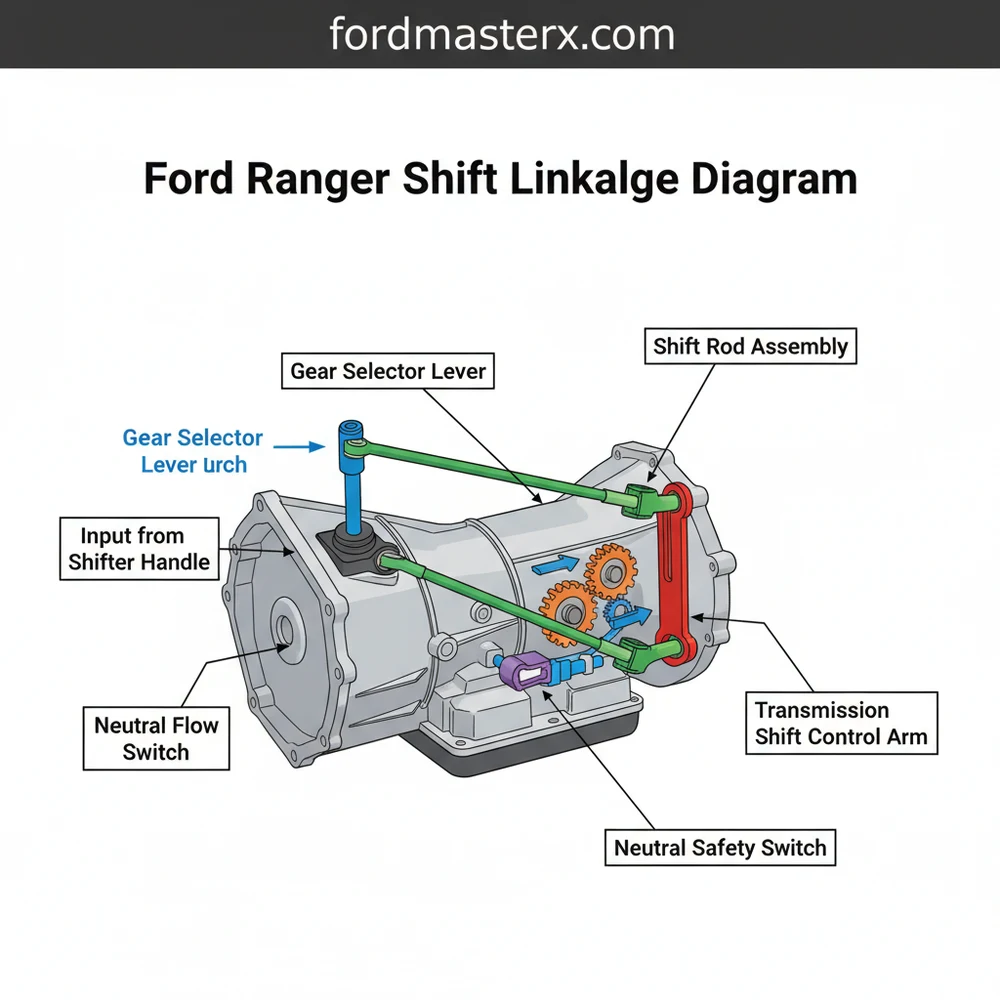
What does this shift linkage diagram show?
This diagram shows the complete mechanical structure of the shifting system. It details how the shift lever, cable, and transmission arm interact. By studying the layout, you can identify specific hardware points, pivot locations, and adjustment nuts necessary for maintaining a crisp, responsive gear selection process for your truck.
How many connections does the shift linkage have?
Most Ford Ranger shift linkage systems consist of two primary connection points: one at the shifter base and one at the transmission range sensor or lever. These are often joined by a single heavy-duty cable or a series of metal rods, depending on the specific year and component design.
What are the symptoms of a bad shift linkage?
A bad shift linkage typically manifests as a loose gear shifter, difficulty engaging specific gears, or the indicator not aligning with the actual gear. If you notice grinding sounds or the vehicle failing to start because it isn’t fully in park, the system configuration likely needs a thorough inspection.
Can I replace the shift linkage myself?
Replacing or adjusting shift linkage components is a moderate DIY task. While the process is straightforward, accessing the configuration often requires crawling under the vehicle and using basic hand tools. As long as you follow the diagram and safety protocols, most owners can handle this repair successfully in their garage.
What tools do I need for this task?
To work on the shift linkage, you will generally need a socket set, a flat-head screwdriver for prying clips, and potentially some pliers. High-quality grease is also recommended for lubricating the bushings. Always use jack stands for safety if you are raising the vehicle for better component access.


