Ford Ranger Fuse Box Diagram: Easy Setup Guide
The 1992 Ford Ranger fuse box diagram labels the interior panel located under the driver-side dashboard and the engine compartment power distribution box. These layouts are essential for identifying failed fuses powering the ECU or ignition system, helping you clear a check engine light or restore vehicle functionality quickly.
📌 Key Takeaways
- Identifies both cabin and engine bay fuse locations
- Crucial for troubleshooting power loss to the ECU
- Prevents electrical fires by ensuring correct amperage use
- Provides a roadmap for fixing a persistent check engine light
- Saves time during emergency roadside electrical repairs
Navigating the electrical system of a classic pickup can be a daunting task, especially when a sudden failure leaves you stranded or without essential accessories. If you are currently troubleshooting an electrical gremlin, having an accurate 1992 Ford Ranger fuse box diagram is the most critical tool in your arsenal. This guide serves as a comprehensive roadmap to help you identify specific circuits, understand the amperage requirements for various components, and bridge the gap between simple fuse replacement and complex electrical diagnostics. Whether you are dealing with a stubborn check engine light or a total loss of cabin power, understanding this diagram will empower you to perform your own repairs with confidence.
The 1992 Ford Ranger utilizes two primary electrical centers: the Interior Fuse Panel located under the dashboard and the Power Distribution Box located in the engine compartment. Both must be inspected when diagnosing systemic electrical issues.
Main Diagram Description and Layout
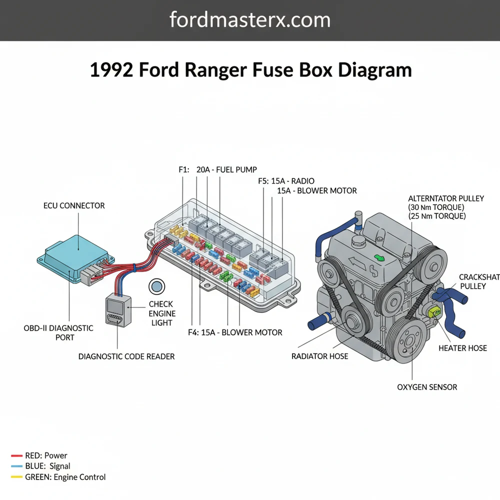
The 1992 Ford Ranger features a centralized electrical architecture that was advanced for its era. The interior fuse box, typically found to the left of the steering column behind a plastic access panel, contains the fuses for the majority of the vehicle’s “low-load” cabin electronics. This includes the radio, instrument cluster, interior lighting, and turn signals. The diagram for this panel is usually printed on the inside of the plastic cover, though years of heat and use often make these labels illegible.
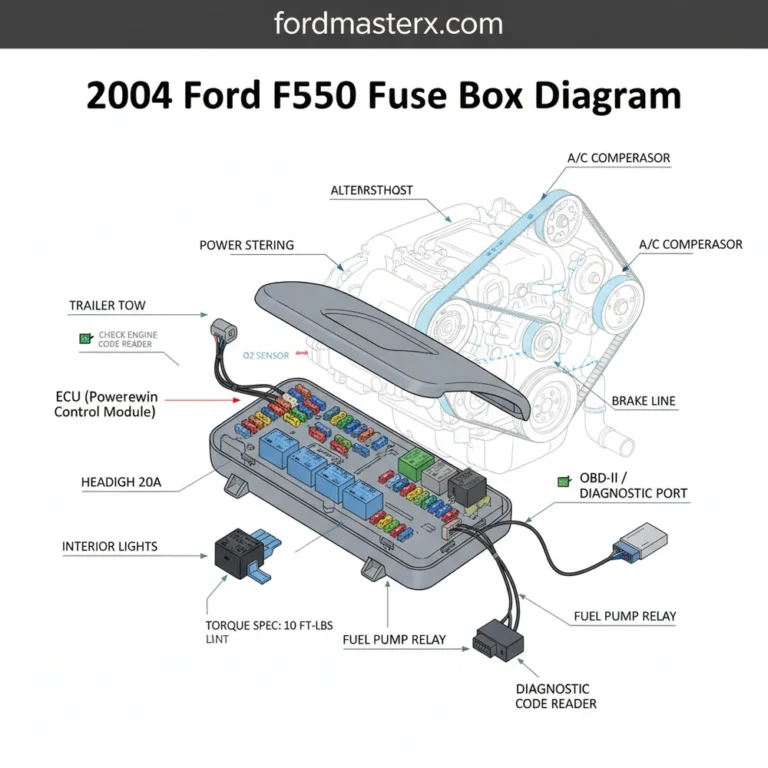
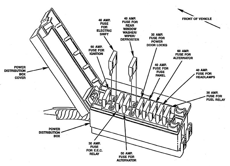
The engine bay contains the Power Distribution Box (PDB), which houses high-amperage “Maxi-fuses” and relays. This secondary diagram is vital because it protects heavy-duty circuits such as the fuel pump, the anti-lock brake system (ABS), and the ECU (Engine Control Unit). The PDB is color-coded; for example, yellow typically represents a 20-amp circuit, while light blue indicates a 15-amp circuit. Understanding these color codes allows for quick visual confirmation during a roadside inspection.
In this diagram, each slot is numbered sequentially. For example, Fuse 1 in the interior panel generally controls the cigarette lighter and horn, while higher-numbered slots may handle the heater blower motor. It is important to note that while the 1992 model year follows a standard template, variations may exist between the 2.3L four-cylinder engine and the 3.0L or 4.0L V6 models, particularly regarding the cooling fan relays and charging system configurations.
[DIAGRAM_PLACEHOLDER: Detailed 1992 Ford Ranger Fuse Box Mapping showing Interior Panel and Engine Power Distribution Box with Amperage Labels]
Step-by-Step Guide to Interpreting and Using the Diagram

Reading a 1992 Ford Ranger fuse box diagram requires a systematic approach to ensure you do not accidentally damage sensitive electronics like the ECU or trip a diagnostic code. Follow these steps to effectively utilize the diagram for your repair needs:
- 1. Locate the Relevant Panel: If your issue is internal (lights, radio), start with the cabin panel. If the truck won’t start or the engine is stumbling, go directly to the engine bay Power Distribution Box.
- 2. Identify the Blown Circuit: Cross-reference the failed component with the diagram. If your “check engine light” is on but the diagnostic tool cannot communicate with the vehicle, look for the fuse labeled “EEC” or “Data Link,” as these power the diagnostic circuits.
- 3. Prepare Your Tools: You will need a plastic fuse puller (usually found inside the box cover) and a digital multimeter or a simple test light. Avoid using metal pliers, which can short out adjacent circuits.
- 4. Perform a Visual Inspection: Pull the suspected fuse and look at the metal filament inside the plastic casing. If the “U” shaped wire is broken or the plastic is charred, the fuse is blown.
- 5. Use a Multimeter for Verification: Set your multimeter to the Continuity or Ohms setting. Touch the probes to the two small metal contact points on the back of the fuse while it is still installed. A “beep” or a zero reading indicates the fuse is good.
- 6. Check Related Mechanical Systems: Electrical issues are often symptoms of mechanical stress. For instance, if the alternator fuse keeps blowing, check the tension on your accessory belt. A slipping belt can cause voltage spikes that pop fuses.
- 7. Replace with Correct Amperage: Never replace a 10-amp fuse with a 20-amp fuse. Doing so can cause the wiring harness to melt or catch fire before the fuse has a chance to blow.
- 8. Reset and Test: Once replaced, turn the ignition to the “On” position. If the fuse blows immediately, you have a “short to ground” that requires deeper investigation into the wiring harness.
Always disconnect the negative battery terminal before working on high-amperage Maxi-fuses in the Power Distribution Box. Failure to do so can result in electrical shock or damage to the sensitive ECU circuitry.
Common Issues and Troubleshooting
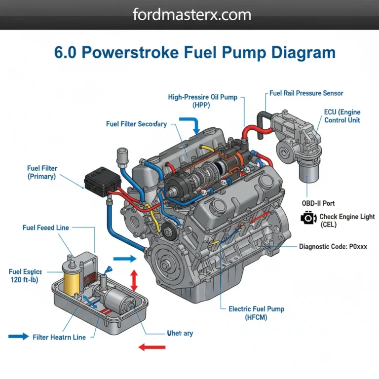
One of the most frequent problems owners of a 1992 Ranger encounter is a failure in the fuel pump relay circuit. If the truck cranks but won’t fire, the PDB diagram will point you toward the Fuel Pump Relay and its associated 20A or 30A fuse. Another common issue involves the “check engine light” failing to illuminate during the bulb-check phase (when the key is first turned). This often traces back to a blown fuse in the interior panel that provides power to the instrument cluster logic.
While the 1992 Ford Ranger utilizes an EEC-IV diagnostic system (predating the modern OBD-II standard), the fuse box remains the heart of the diagnostic process. If you are trying to pull a diagnostic code using a jumper wire or an analog code reader, a blown fuse will prevent the system from entering self-test mode. Furthermore, if you notice your truck is overheating, don’t immediately assume the timing chain has skipped or the water pump is failing; check the fuse box diagram for the electric cooling fan relay. If this relay fails, the lack of coolant flow through the radiator while idling will cause rapid temperature spikes.
Tips and Best Practices for Maintenance
Maintaining the electrical integrity of your Ford Ranger requires more than just replacing fuses when they pop. Over time, the contacts within the fuse box can succumb to corrosion, especially in the engine bay where moisture and road salt are prevalent. Periodically cleaning these contacts with specialized electronic cleaner can prevent phantom electrical issues and voltage drops.
If you are experiencing intermittent power loss, check the torque spec of your battery terminal clamps and the main power wire leading to the distribution box. A loose connection here can mimic multiple blown fuses.
When performing larger maintenance tasks, such as replacing the accessory belt or inspecting the timing chain area, always take a moment to look for frayed wires near the engine block. Heat cycles can make the wire insulation brittle, leading to shorts that will eventually manifest in the fuse box. Additionally, ensure your coolant flow is unobstructed; excessive engine heat can actually increase the resistance in nearby wiring harnesses, leading to premature fuse failure in the engine bay panel.
Finally, always keep a spare kit of “ATM” (mini) and “MAXI” fuses in your glovebox. Using high-quality, name-brand fuses is a cost-saving measure in the long run, as cheap, unrated fuses may not blow at the correct amperage, potentially leading to expensive damage to the ECU or other vital controllers. By following the 1992 Ford Ranger fuse box diagram and adhering to these maintenance standards, you can keep your vintage truck reliable for years to come.
- ✓ Always match the fuse color and number to the diagram specifications.
- ✓ Keep the fuse box covers tightly sealed to prevent moisture entry.
- ✓ Verify ground connections on the chassis if multiple fuses blow simultaneously.
- ✓ Consult a professional if you smell burning plastic or see smoke from the dashboard.
Frequently Asked Questions
Where is the fuse box located?
The primary fuse box is located inside the cabin, positioned behind the dash panel to the left of the steering column. A secondary high-power distribution box is situated under the hood, typically near the battery on the driver-side fender well, housing larger fuses and relays.
What does the diagram show?
The diagram provides a visual map of all electrical circuits, showing the specific amperage for each fuse and the function of every relay. It illustrates how power flows to critical components like the ECU and headlights, which is vital for diagnosing complex electrical failures.
How many fuses does the Ranger have?
The 1992 model typically features around 18 to 24 fuses in the interior panel, plus several high-current maxi-fuses and relays in the engine compartment. Each circuit is color-coded by amperage to prevent overloading sensitive electronics like the ECU or internal diagnostic systems.
What are the symptoms of a bad fuse?
Symptoms include a sudden loss of power to specific components, such as radio failure or interior lights flickering. If a fuse related to the ECU blows, it may trigger a check engine light or prevent the vehicle from communicating with a diagnostic code reader.
Can I replace a fuse myself?
Yes, replacing a fuse is a simple DIY task. Once you identify the blown fuse using the diagram, use a fuse puller to remove the old one and insert a new fuse of identical amperage. Unlike modern OBD-II systems, these older circuits are straightforward for home mechanics.
What tools do I need for this task?
You primarily need a plastic fuse puller and a basic test light to check for continuity. If you are tightening battery terminals while working on the power distribution box, ensure you follow the manufacturer’s recommended torque spec for a secure and safe electrical connection.