Ford Radius Arm Bushing Diagram: Visual Component Guide
A Ford radius arm bushing diagram displays the assembly of the bushing, spacers, and heat shields onto the radius arm. This configuration secures the arm to the frame bracket, maintaining front-end alignment and dampening vibrations within the front suspension system for smoother vehicle stability and operation.
📌 Key Takeaways
- Identifies the correct order of washers and bushings on the arm
- The frame bracket is the primary anchor point to locate
- Always replace both sides to ensure balanced suspension geometry
- Check for heat shield presence to prevent premature bushing failure
- Use this diagram during suspension overhauls or alignment fixes
If you have noticed a persistent clunking sound coming from the front end of your vehicle or if your steering feels increasingly vague and unstable, you likely need a professional ford radius arm bushing diagram to help diagnose and repair the issue. These diagrams serve as an essential blueprint for anyone working on the front suspension systems of Ford trucks and SUVs. Understanding the structural layout of these components is the first step in restoring your vehicle’s handling and safety. In this guide, we will break down the entire radius arm assembly, explain how to interpret the schematic, and provide a detailed roadmap for replacing worn components to ensure your suspension performs as intended.
The Anatomy of a Radius Arm Assembly
The radius arm system is a fundamental component of the front suspension configuration found in many Ford vehicles, particularly those utilizing the Twin I-Beam or 4WD solid axle setups. The primary purpose of the radius arm is to control the fore and aft movement of the front axle. Without these arms, the axle would shift during acceleration and braking, leading to catastrophic handling failures. A comprehensive ford radius arm bushing diagram typically illustrates an exploded view of how the arm connects to the frame bracket.
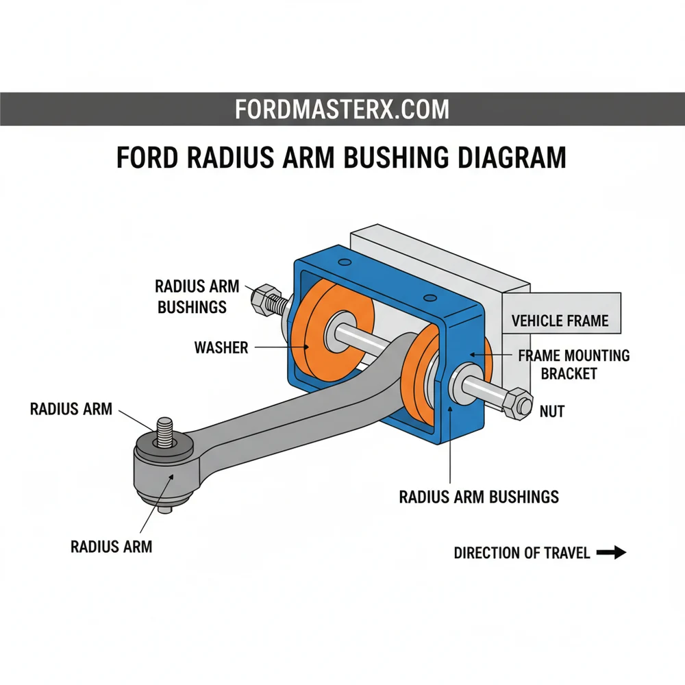
At the center of this system is the radius arm itself, a heavy-duty steel beam that bolts to the axle at the front and passes through a frame-mounted bracket at the rear. The “bushing” is the critical interface where the arm meets the frame. This interface is not a single piece but a multi-part assembly designed to absorb road vibrations while allowing for necessary suspension travel.
A standard overview of the components includes:
- ✓ The Radius Arm: The structural backbone connecting the axle to the frame.
- ✓ The Rear Bracket: A heavy-duty steel mount riveted or bolted to the vehicle frame.
- ✓ Inner and Outer Bushings: Two rubber or polyurethane donuts that sandwich the bracket.
- ✓ The Plastic Spacer/Sleeve: Often found between the bushings to prevent over-compression.
- ✓ Washers and Nuts: Large cupped washers that hold the bushings in place and a heavy-duty lock nut.
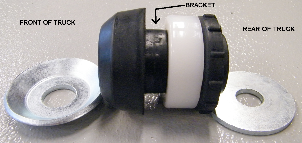
In many configurations, the passenger-side diagram will also feature a heat shield. This is a vital component because the exhaust manifold is often positioned close to the radius arm bracket on that side. The shield prevents the extreme heat from prematurely melting or cracking the rubber bushing material. When reviewing your schematic, pay close attention to the orientation of the cupped washers; they must face inward to properly seat the bushings.
[DIAGRAM_PLACEHOLDER: Exploded view showing Radius Arm, Front Washer, Front Bushing, Frame Bracket, Rear Bushing, Rear Washer, and Nut.]
Most Ford radius arm diagrams utilize a “stacked” visual representation. This means the parts are shown in the exact order they must be slid onto the threaded end of the radius arm. Reversing the order of the washers or omitting the spacer can lead to rapid bushing failure and poor alignment.
How to Read and Apply the Diagram for Installation
Reading a suspension schematic can be intimidating for a beginner, but it follows a logical linear progression. The diagram usually starts from the front of the vehicle (left side of the paper) and moves toward the rear. To use the ford radius arm bushing diagram effectively during a repair, follow these systematic steps to ensure the system is restored to factory specifications.
Step 1: Preparation and Safety
Before consulting the diagram, ensure the vehicle is safely supported. Use high-capacity jack stands on the frame rails, not the axle. Removing the radius arm nut will allow the axle to move, so it is critical that the frame is immobilized. You will need a large 1-1/8 inch or 1-1/16 inch socket, a heavy-duty breaker bar, and potentially a pneumatic impact wrench.
Step 2: Component Identification
Locate the threaded end of the radius arm protruding through the rear bracket. Compare what you see on the vehicle to the layout in the schematic. Identify the nut, the outer washer, and the visible portion of the bushing. If the bushings are original, they may be distorted or partially missing due to rot.
Step 3: Disassembly and Cleaning
Remove the large nut and the outer washer. In many cases, you do not need to remove the entire radius arm from the vehicle. By using a ratchet strap (come-along) attached to the front axle and a stationary point toward the front of the vehicle, you can pull the axle forward just enough to slide the radius arm out of the frame bracket. Once the arm is clear, remove the old bushing remnants. Clean the threaded end of the arm and the hole in the bracket with a wire brush to remove rust and debris.
Step 4: Installing the Inner Components
Refer back to your diagram for the “Inner” stack. Slide the first cupped washer onto the arm (cup facing toward the bracket). Slide the inner bushing onto the arm. If your kit includes a plastic or metal sleeve, slide it on now. This sequence is the most common point of error, so double-check the schematic to ensure the bushing is oriented correctly.
Step 5: Seating the Arm into the Bracket
Slowly release the tension on your ratchet strap to allow the radius arm to slide back into the hole in the frame bracket. Ensure the inner bushing seats firmly against the bracket face.
Step 6: Completing the Outer Stack
Once the threaded end is through the bracket, install the outer bushing, followed by the outer cupped washer (cup facing the bracket). Finally, thread the nut onto the arm.
Step 7: Final Torque
Do not fully tighten the nut while the vehicle is in the air. Lower the vehicle so the suspension is under its own weight (ride height). Use a torque wrench to tighten the nut to the specification listed in your service manual—typically between 80 and 120 foot-pounds. This ensures the bushings are compressed to the correct density.
Never apply grease or oil to rubber bushings unless the manufacturer specifically recommends it. Petroleum-based lubricants can break down rubber, causing it to soften and fail within weeks. For polyurethane bushings, use only the specialized synthetic grease provided in the kit.
Common Issues and Troubleshooting the Radius Arm System

Even with a perfect ford radius arm bushing diagram, you may encounter complications during the repair process. One of the most common issues is “bracket ovaling.” This occurs when a bushing has been worn out for so long that the metal radius arm begins to rub directly against the hole in the frame bracket. Over time, the round hole becomes an oval shape. If you install new bushings into an ovaled bracket, they will have too much room to move, leading to immediate clunking and premature failure. If the hole is no longer perfectly round, the bracket must be replaced or repaired by welding.
Another frequent problem is the “stuck nut.” Because these components are located underneath the vehicle, they are subjected to road salt, water, and heat. The radius arm nut is notorious for seizing.
Signs that your radius arm bushings have failed include:
- ✓ Metallic Clunking: Occurs specifically when hitting bumps or during heavy braking.
- ✓ Steering Wander: The vehicle “darts” left or right and requires constant correction.
- ✓ Uneven Tire Wear: Usually manifested as “cupping” on the inner or outer tread.
- ✓ Brake Pull: The vehicle pulls hard to one side because the axle is shifting under braking force.
If you see these symptoms, use the diagram to verify that all hardware is present. Sometimes, a previous owner may have omitted a washer, causing the bushing to push through the bracket hole.
Tips and Best Practices for a Successful Repair
When choosing replacement parts based on your ford radius arm bushing diagram, you will likely have to choose between rubber and polyurethane. Rubber bushings offer a softer, quieter ride and are excellent for daily drivers. However, polyurethane bushings are much more durable and provide a “firmer” steering feel, making them ideal for lifted trucks or vehicles used for heavy towing.
If your vehicle’s radius arm brackets are riveted to the frame (standard from the factory), and you find they are damaged, do not attempt to re-rivet them. Instead, grind the rivet heads off, punch out the bodies, and replace the bracket using high-grade (Grade 8) bolts and locking nuts. This makes future maintenance much easier.
Maintenance recommendations for this system are relatively simple but effective. Every time you change your oil, perform a visual inspection of the radius arm brackets. Look for cracks in the rubber or orange “dust,” which is often a sign of metal-on-metal contact. If you live in a rust-prone area, applying a lanolin-based undercoating to the bracket area can prevent the nuts from seizing.
Lastly, always perform a front-end alignment after replacing radius arm bushings. Because these components control the “caster” and “toe” angles of your front wheels, even a slight change in bushing thickness can throw your alignment out of specification. Investing in a professional alignment will protect your new bushings and extend the life of your tires. By following the correct ford radius arm bushing diagram and adhering to these best practices, you can ensure your vehicle remains stable, predictable, and safe on the road for years to come.
Step-by-Step Guide to Understanding the Ford Radius Arm Bushing Diagram: Visual Component Guide
Identify the assembly – Start by identifying all parts in the diagram to ensure you have the correct replacement kit.
Locate the bracket – Locate the frame bracket where the radius arm connects and spray the nut with penetrating oil.
Understand the sequence – Understand how the washers and bushing halves sandwich the frame bracket by studying the diagram layout.
Apply the bushings – Connect the new front bushing and washer onto the arm before sliding it through the frame bracket.
Verify the alignment – Verify that the rear bushing and concave washer are seated properly before starting the nut by hand.
Complete the torque – Complete the installation by tightening the nut to the specific foot-pounds required for your Ford model’s configuration.
Frequently Asked Questions
Where is the radius arm bushing located?
The radius arm bushing is located at the rear end of the radius arm where it attaches to the vehicle frame bracket. It sits behind the front wheel, acting as a pivot point between the front axle assembly and the chassis to manage fore and aft movement.
What does this diagram show?
This diagram shows the complete internal structure and layout of the radius arm assembly. It highlights the sequence of the front washer, the rubber or polyurethane bushing halves, the frame bracket interface, the rear washer, and the final securing nut in the system configuration.
How many components are in the bushing assembly?
A standard Ford configuration typically consists of five main pieces per side: a front large washer, a front bushing half, the frame bracket (not replaced), a rear bushing half, and a rear concave washer. All these are secured by a single large nut at the end.
What are the symptoms of a bad radius arm bushing?
Common symptoms include a loud clunking noise when hitting bumps or braking, wandering steering, and uneven tire wear. If the component structure fails, you may feel the front end ‘shift’ during acceleration or deceleration as the arm moves excessively within the frame bracket.
Can I replace this myself?
Yes, replacing these bushings is a common DIY task. While the process requires heavy-duty tools like a large torque wrench and jack stands, following a diagram makes the assembly sequence clear. It is often easier to remove the bracket bolts rather than the arm itself.
What tools do I need for this task?
You will need a floor jack, jack stands, a 1-1/8 inch socket or wrench for the nut, and potentially a breaker bar. A torque wrench is essential to ensure the system is tightened to factory specifications to prevent the hardware from loosening during vehicle operation.