Ford PATS System Reset: The Definitive Technical Guide to SecuriLock, Diagnostics, and Programming
The Ford Passive Anti-Theft System (PATS), commercially designated as SecuriLock, represents one of the most significant advancements in automotive security architecture of the late 20th and early 21st centuries. Introduced in 1996 to combat the rising tide of vehicle theft via “hot-wiring” and slide-hammer ignition attacks, PATS fundamentally altered the relationship between the driver, the key, and the engine management system.
For the modern automotive technician, locksmith, or advanced enthusiast, PATS is not merely a barrier to theft; it is a complex, distributed network of electronic modules that requires a sophisticated understanding of Radio Frequency Identification (RFID), Controller Area Network (CAN) bus protocols, and cryptographic authentication procedures.
This comprehensive research report serves as an exhaustive reference for diagnosing, resetting, and programming the Ford PATS system. Moving beyond superficial “quick fix” tutorials, this document dissects the underlying engineering logic of the system, tracing its evolution from the rudimentary Type A standalone modules to the highly integrated Type G and Intelligent Access (PEPS) systems of the modern era.
We will explore the physics of the transponder-transceiver relationship, the critical distinctions between 40-bit and 80-bit encryption architectures—a frequent source of confusion during the 2009–2011 transition years—and the granular diagnostics provided by the system’s “Morse code” flash signals.
Furthermore, this report provides detailed, step-by-step technical workflows for executing system resets, performing parameter resets following module replacement, and programming keys using industry-standard tools like FORScan.
By synthesizing data from technical service bulletins, engineering documentation, and field-tested diagnostic protocols, this report aims to be the final authority on Ford PATS reset procedures.
Ford PATS System Reset
Comprehensive data, cost analysis, and reset procedures for the Passive Anti-Theft System.
What is the PATS System?
The Passive Anti-Theft System (PATS), also known as SecuriLock, disables your engine if a recognizable key is not detected. It uses an RFID transponder inside the key head. If the transceiver in the steering column doesn’t recognize the code, the fuel pump is disabled, and the theft light flashes rapidly.
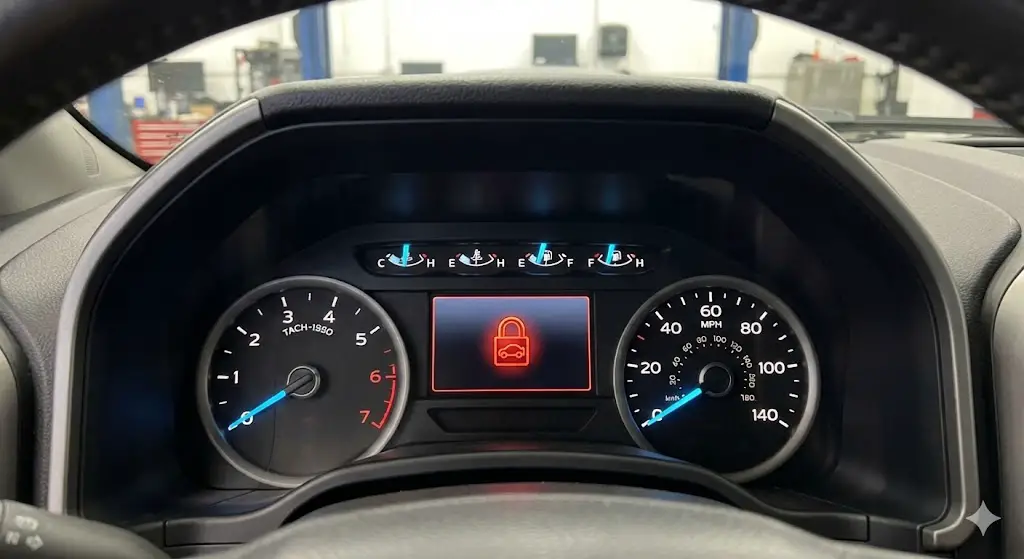
The “Rapid Flash” Indicator
A rapidly flashing theft light (once per second) is the primary indicator of a PATS lockout. This means the vehicle is immobilized. It is not a starter failure; it is a security intervention.
Method Analysis: Cost vs. Time
Choosing how to reset your system depends on your budget and urgency. We compared the three most common methods: The DIY Key Cycle, hiring a Mobile Locksmith, and towing to a Dealership.
DIY Method
Lowest cost, but requires 45+ minutes of waiting. High risk of user error.
Locksmith
Balanced option. They come to you, usually within hours. Moderate cost.
Dealership
Highest reliability but most expensive due to towing and labor rates.
Data estimated based on 2024 national averages.
The 45-Minute DIY Reset Procedure
If you have two keys or need to synchronize a new PCM, this “Key Cycling” method is the standard DIY approach. No tools required.
Insert Key
Insert the first key into the ignition and turn it to the ON position (Run). Do not crank the engine.
Observe Light
Watch the security light. It will remain solid for 15 minutes before turning off.
Cycle Off/On
Within 5 minutes of the light going out, turn Key OFF and back to ON. Repeat 3 times total.
Start Engine
After the 3rd cycle (approx 45 mins), the key code is learned. Attempt to start the engine.
⚠ NOTE: This procedure works for PATS 1 & 2 systems. Newer CAN-bus systems (2010+) may require OBD-II tools like FORScan.
Diagnostics: Reading Blink Codes
If the theft light flashes rapidly, wait 60 seconds. It will stop and then begin to flash a 2-digit code (e.g., 1 flash, pause, 6 flashes = Code 16). Understanding these codes is critical for fixing the root cause rather than just resetting the system.
- Code 16 CAN Link Error: The Cluster cannot communicate with the PCM. Often a wiring issue or blown fuse.
- Code 13 Key Not Received: The transceiver did not detect a key. Likely a bad key transponder.
- Code 15 Invalid Key: The key was read, but the code does not match memory. Requires programming.
- Code 11 Transceiver Disconnected: The antenna ring around the ignition is unplugged or broken.
Success Rate by Method
Probability of a successful engine start on the first attempt.
Theoretical Framework and System Architecture
The Philosophy of Passive Immobilization
To understand how to reset or repair the PATS system, one must first grasp its design philosophy. Prior to the mid-1990s, vehicle security was largely defined by active alarms—systems that required user intervention, such as pressing a fob button to arm or disarm the vehicle, or mechanical barriers like steering column locks. These systems had a critical weakness: if the user failed to arm the system, or if the mechanical lock was physically defeated, the engine could be started.
PATS introduced the concept of passive immobilization. The system is "passive" because it requires no deliberate action from the driver other than the standard act of inserting the key and turning the ignition. There are no buttons to press, no codes to punch into a keypad, and no batteries to replace in the key head (for the transponder function). The security is inherent to the physical key itself.
The core objective of PATS is not necessarily to prevent entry into the vehicle cabin—perimeter alarms handle that function—but to strictly prevent sustained internal combustion. In many PATS implementations, the system allows the starter motor to engage and crank the engine. This design choice often confuses technicians, leading to misdiagnosis of fuel pump failures or ignition system faults. However, while the engine cranks, the Powertrain Control Module (PCM) deliberately disables the fuel injectors and, in some cases, the ignition coil drivers. If the cryptographic "handshake" between the key and the transceiver fails, the engine may fire briefly on residual fuel vapors but will immediately die, or simply crank indefinitely without firing.
The Physics of Automotive RFID: The 134.2 kHz Handshake
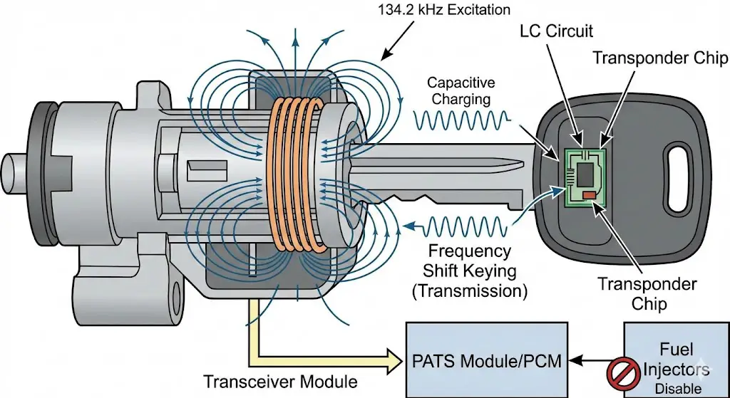
At the microscopic level, the PATS system operates on the principles of Low-Frequency (LF) Radio Frequency Identification. The interaction is a sequence of electromagnetic events that must occur within hundreds of milliseconds of the ignition key being turned to the RUN position.
- Inductive Coupling (Excitation):Surrounding the mechanical ignition lock cylinder is a component known as the Transceiver Module. This module contains a copper coil antenna. When the driver turns the key, the PATS control module sends a voltage signal to the transceiver, causing it to oscillate and generate a low-frequency electromagnetic field, typically tuned to 134.2 kHz. This field is the "question" asked by the car.
- Capacitive Charging (Energization):The PATS key contains a transponder chip embedded in the plastic head. This chip is a passive device; it has no internal power source. Inside the chip is a tiny LC circuit (inductor-capacitor). When the key is placed in the transceiver's magnetic field, the coil in the key absorbs the energy via induction, charging the capacitor. This process powers the microchip.
- Frequency Shift Keying (Transmission):Once energized, the transponder chip uses the stored energy to transmit a unique digital signature back to the transceiver. It does this by modulating the magnetic field—essentially "loading" and "unloading" the field in a pattern that corresponds to its binary identification code. This is the "answer" given by the key.
- Demodulation and Verification:The transceiver detects these minute modulations, converts them into a digital hexadecimal string, and forwards this data to the controlling module (PATS Module, Instrument Cluster, or PCM). The module compares this hexadecimal string against a stored "White List" of authorized keys in its Non-Volatile Random Access Memory (NVRAM).
- Challenge-Response (Advanced Encryption):In early systems (Texas Instruments 4C), the key simply shouted its ID number (Fixed Code). In later iterations (Texas Instruments 4D-63 and 80-bit systems), the vehicle employs a "Challenge-Response" mechanism. The car sends a random number (a nonce) to the key. The key processes this number using a secret internal algorithm and transmits the calculated result back to the car. This prevents "replay attacks," where a thief records the signal of a valid key and plays it back later to trick the car.
System Topologies: The Evolution of "Control Function Types"
One of the most pervasive sources of confusion in Ford diagnostics is the location of the PATS "brain." It is not a single, static component across all models. Ford engineers migrated the PATS logic through various modules over the decades to increase security and integration. These configurations are categorized as Control Function Types (A through G). Understanding which type a vehicle employs is critical for determining the correct reset procedure.
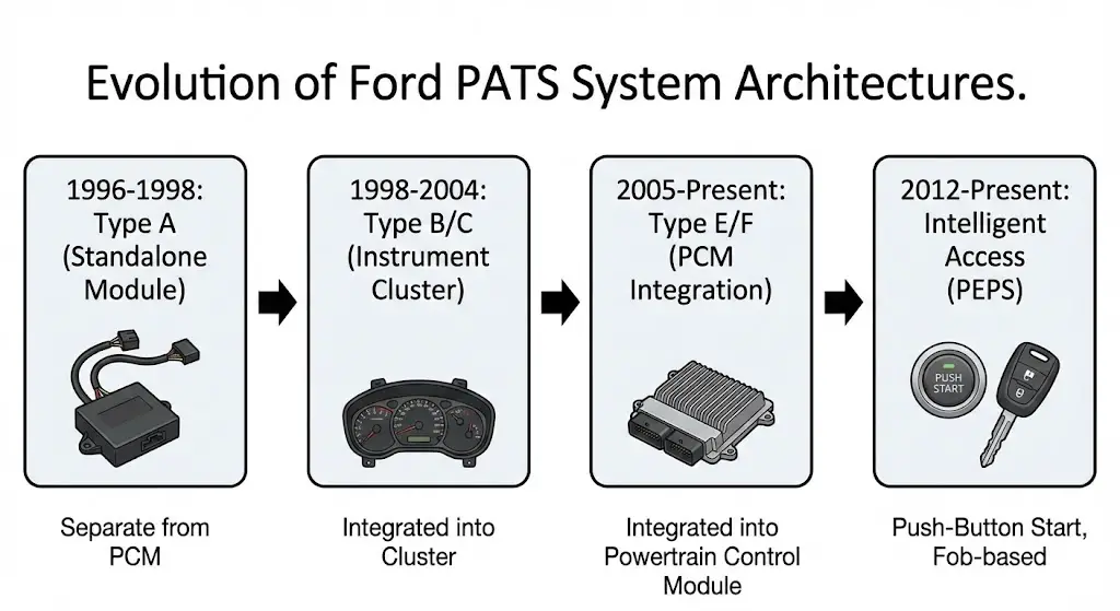
Type A & D: The Standalone Era (1996–1998)
In the genesis of PATS, the logic resided in a dedicated, standalone module—often a small box located behind the dashboard, separate from the PCM and the Instrument Cluster.
- Operation: The standalone module read the key. If valid, it sent a simple "Enable" signal to the PCM.
- Vulnerabilities: These systems were susceptible to "bypass" modules that could emulate the simple enable signal, allowing thieves to hot-wire the car once they bypassed the lock cylinder.
- Reset Procedure: These systems often utilized a time-based initialization where a new module could be synced simply by leaving the ignition on, as they lacked the complex encrypted handshake of later CAN-bus systems.
Type B & C: The Instrument Cluster Era (1998–2004+)
To reduce costs and increase security, Ford integrated the PATS logic into the Instrument Cluster, specifically the Hybrid Electronic Cluster (HEC) or Virtual Image Cluster (VIC).
- The "Marriage" Concept: In this topology, the Cluster and the PCM are "married." The Cluster authenticates the key, and if satisfied, sends an encrypted data packet over the Standard Corporate Protocol (SCP) bus to the PCM.
- Service Implication: If a technician replaces a faulty instrument cluster (e.g., due to dead gauges), the car will not start. The new cluster has a different security ID than the PCM expects. This requires a Parameter Reset to introduce the new cluster to the old PCM.
- Common Vehicles: Ford Mustang (1999-2004), Ford F-150 (1999-2003), Ford Focus (2000-2004).
Type E & F: The PCM Integration Era (2005–Present)
With the advent of faster CAN-bus architectures, the PATS logic was moved directly into the Powertrain Control Module (PCM). The Instrument Cluster was demoted to a mere gateway—it receives the key signal from the transceiver and passes it raw to the PCM for processing.
- Security: This is more robust because the module controlling the engine is the same module verifying the key. There is no "Enable" signal to intercept between boxes.
- Service Implication: Replacing the PCM now means you are replacing the PATS system itself. You must program at least two new keys into the new PCM because the old key data lived in the old PCM.
- Common Vehicles: Ford F-150 (2004+), Ford Fusion, Ford Escape (2005+).
Type G: The Distributed Cluster Module (ICM)
Found in specific global platforms like the Ford Focus (European/Global Mk2) and Transit Connect, this system places the logic in the cluster but utilizes a high-speed CAN link for authorization.
- The "Code 16" Phenomenon: This architecture is notorious for Flash Code 16 (CAN Link Failure). Because the Cluster and PCM must talk constantly to maintain engine operation, any degradation in the CAN wiring or the cluster's circuit board connector (a common failure on 2005-2008 Focus models) results in an immediate mobilization.8
The Hardware Ecosystem – Transponders and Keys
A successful PATS reset or key programming operation is impossible if the hardware is incompatible. Ford has utilized several generations of transponder technology, supplied primarily by Texas Instruments.
Transponder Generations and Compatibility
| Technology | Bit Depth | Chip ID | Market Name | Key Blank Examples | Era | Characteristics |
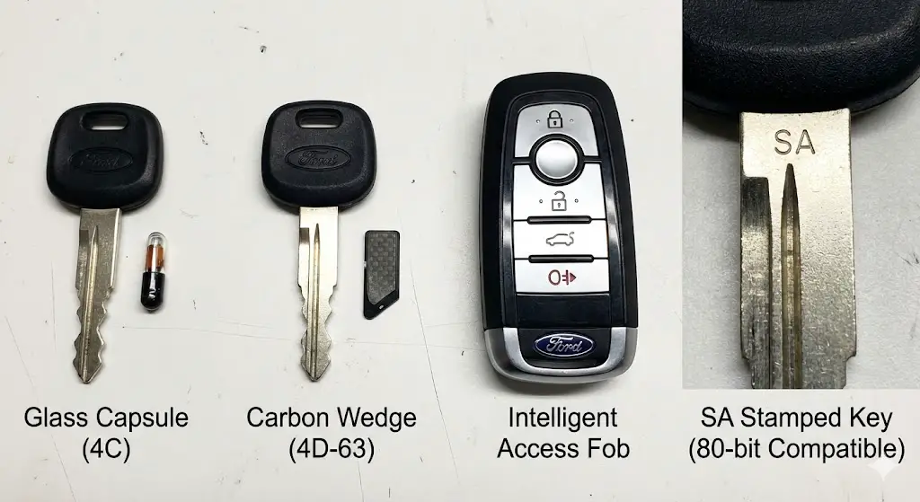
| Glass Capsule | 40-Bit | 4C | T.I. Fixed Code | H72, H74 | 1996–2002 | A small glass ampoule inside the key. Fixed code (no challenge-response). Cannot be cloned to standard chips easily without specialized emulators. |
| Carbon Wedge | 40-Bit | 4D-63 | T.I. Crypto | H75, H84, H92 | 2000–2010 | A black, wedge-shaped carbon chip. Introduced encryption. Highly reliable. |
| High Encryption | 80-Bit | 4D-63+ / 4D-83 | T.I. DST+ | H92, H94, H128 | 2011–2019 | Enhanced security with 80-bit encryption. Physically identical to the 40-bit wedge but logically different. |
| Intelligent Access | 128-Bit | Hitag Pro / T.I. | PEPS | Smart Fob | 2012–Present | Used in push-button start vehicles. Supports proximity detection and bidirectional long-range communication. |
The 40-bit vs. 80-bit Transition Crisis (2009–2011)
One of the most complex aspects of modern PATS diagnostics involves the transition period between 2009 and 2011, where Ford migrated from 40-bit to 80-bit encryption. This period creates significant confusion for locksmiths and technicians.4
The "SA" Stamp Myth:
Many Ford keys from this era are stamped with the letters "SA" on the blade. There is a prevalent myth that "SA" keys are strictly 80-bit.
- Reality: The "SA" stamp indicates the key is 80-bit Compatible. It contains a chip capable of 80-bit encryption. However, this chip is backward compatible. It can be programmed into a 40-bit vehicle (e.g., a 2008 F-150) and will function as a 40-bit key.
- The Trap: While an 80-bit key works in a 40-bit car, a 40-bit key (older stock H84) will NOT work in an 80-bit car (e.g., 2013 F-150). If you attempt to program a 40-bit key into an 80-bit system, the procedure will fail, often throwing a Code 13 or Code 15 (Invalid Key).
Voltage Diagnostics:
To definitively determine if a vehicle requires 80-bit encryption without looking up the VIN, technicians can measure the voltage at the 4-pin Immobilizer (Transceiver) connector 4:
- 40-Bit System: May show pulsed voltage.
- 80-Bit System: typically shows specific voltage states:
- No Key: 0V
- Key in (Ignition OFF): +12V
- Key in (Ignition ON): +12V
The Transceiver Ring: Failure Modes
The transceiver is the physical interface between the car's electronics and the key. While robust, it is subject to physical damage, particularly in fleet vehicles where heavy keychains swing and impact the steering column.
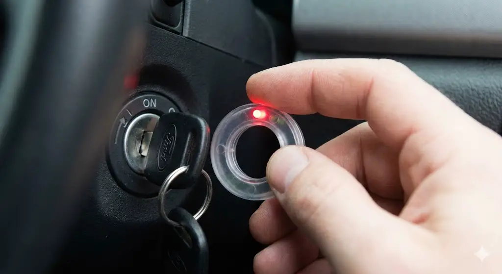
- Symptoms of Failure: If the transceiver coil breaks (open circuit), it cannot energize the key. The PATS module will detect this open circuit and flash Code 12 (Bad Transceiver Coil). If the wiring to the module is severed, it will flash Code 11 (Transceiver Not Connected).
- Testing: A simple "Inductive Ring Tester" or "Sniffer" is an essential tool. When held against the ignition lock while turning the key, the tester's LED should light up, confirming the transceiver is emitting the 134 kHz field. No light means no field, pointing to a transceiver or wiring fault.13
Diagnostic Protocols – Reading the "Morse Code"
Before attempting any reset, effective diagnosis is mandatory. Ford provides a highly effective built-in diagnostic interface via the Theft Indicator Light. This LED, located on the dashboard or instrument cluster, communicates specific fault codes through a flashing sequence, similar to Morse code or OBD-I flash codes.
The Diagnostic Sequence
- Trigger Event: Insert the key and turn the ignition to ON/RUN. Do not crank the engine.
- Observation: If the system is working, the theft light will illuminate for 3 seconds (Prove-Out) and then extinguish.
- Fault Indication: If a fault exists, the light will flash rapidly (approx. 3Hz) for roughly 45–60 seconds.
- Code Transmission: After the rapid flashing stops, the light will pause and then begin flashing a 2-digit code.
- Example: FLASH (pause) FLASH-FLASH-FLASH-FLASH-FLASH-FLASH. This represents Code 16.
- The code will repeat several times.
Comprehensive Flash Code Matrix
The following table synthesizes data from multiple technical sources to provide a definitive guide to PATS flash codes.8
| Flash Code | DTC Equivalent | System State | Detailed Meaning | Recommended Diagnostic Step |
| 11 | B1681 | Immobilized | Transceiver Not Connected. The control module cannot detect the transceiver ring. | Check the 4-pin connector at the transceiver. Check for severed wires in the steering column. |
| 12 | B1681 | Immobilized | Defective Transceiver Coil. The module detects the transceiver is connected but the internal coil is open/shorted. | Replace the transceiver ring. |
| 13 | B1600 | Immobilized | Key Code Not Received. The key is not transmitting data. | Key battery is irrelevant. The transponder is dead, missing (non-chip key), or shielded by other keys/metal on the ring. |
| 14 | B1602 | Immobilized | Partial Key Code. The signal was received but corrupted. | Interference from RFID tags (SpeedPass), metallic key covers, or weak transponder. Try a different key. |
| 15 | B1601 | Immobilized | Invalid Key Code. The key is transmitting a valid code, but it is not in the "White List." | The key is good but unprogrammed. Perform "Add Key" or "All Keys Lost" programming. |
| 16 | U1900 / U2510 | Immobilized | CAN Link Failure. The PCM and Cluster cannot communicate. | CRITICAL: Check Fuse 28 (PCM power). Check Cluster connector solder joints (Focus/F-150). This is rarely a key issue. |
| 21 | B1213 | Immobilized | Below Minimum Keys. The system has been erased but fewer than 2 keys have been programmed. | You must program a second unique key to close the learning cycle. |
| 22 | B2141 | Immobilized | Configuration Error. The PATS module memory is corrupted. | Module replacement is likely required. |
| 23 | U2510 | Immobilized | Security Mismatch. PCM and Cluster ID do not match. | Occurs after swapping a PCM or Cluster. Perform Parameter Reset. |
Deep Dive: The "Code 16" Nightmare
Code 16 is frequently misdiagnosed as a bad key or bad computer, leading to unnecessary component replacement. In reality, Code 16 indicates a breakdown in the nervous system of the vehicle—the CAN bus.
- The Mechanism: In Type B, C, and G systems, the Cluster verifies the key and must tell the PCM "It's safe to start." If the wire connecting them is broken, or if the PCM is unpowered (blown fuse), the Cluster screams into the void. Receiving no acknowledgment from the PCM, it sets Code 16.
- The Fix: On 2004-2008 F-150s and 2005-2007 Focuses, this is often a physical failure of the solder joints on the instrument cluster PCB where the main harness connects. Pressing firmly on the dashboard above the cluster while cranking can sometimes temporarily restore connection, confirming the diagnosis.8
The "Reset" – Terminology and Procedures
In the automotive domain, the term "Reset" is dangerously ambiguous. It can refer to three distinct procedures with vastly different outcomes. Using the wrong "reset" can leave a vehicle permanently immobilized.
The "Theft Light Reset" (System Clear)
This is not a reprogramming event. It is simply clearing a "False Positive" alarm state.
- Scenario: You disconnected the battery, or used a non-chipped key to turn the lock, triggering the rapid theft light.
- Procedure:
- Remove the key.
- Close all doors.
- Wait 45-60 seconds for the system to timeout.
- Insert a valid key and start the vehicle.
- Note: Disconnecting the battery does not fix a PATS fault. The memory is non-volatile. It will retain the fault status and the key list indefinitely without power.17
The "Parameter Reset" (Module Synchronization)
This is the most critical procedure for repair technicians dealing with module failure.
- Scenario: You have replaced the PCM, Instrument Cluster, or BCM. The vehicle has valid keys that physically turn the lock, but the engine cranks and dies. The theft light may flash Code 23.
- Theory: The security modules share a cryptographically paired ID. When you replace a module, the new unit has a different ID (or a blank one). A Parameter Reset forces the modules to exchange credentials and establish a new trust relationship.
- The "Zero Key" Danger:
- On Type B/C systems (Ford Focus/F-150 older): Parameter Reset usually does not erase the keys stored in the Cluster. You simply re-sync the PCM.
- On Type E/F systems (Newer CAN): Parameter Reset may require a subsequent "Key Relearn" where the keys must be cycled again.
- Procedure: This cannot be done manually. It requires a scan tool (FORScan, IDS).7
The "Master Reset" (Erase and Reprogram)
- Scenario: All Keys Lost (AKL), or the customer has had keys stolen and wants them disabled.
- Outcome: This wipes the NVRAM "White List" of all keys.
- The "Two Key" Rule: Ford security architecture mandates a minimum of two keys to close the programming loop. If you perform a Master Reset with only one key in hand, the vehicle will remain in theft mode (Code 21) and will not start until a second key is purchased, cut, and introduced to the system.21
Execution – Step-by-Step Programming Workflows
This section provides the technical workflows for programming, utilizing the two primary methods: the "On-Board" method (Owner Mode) and the "Software Method" (FORScan).
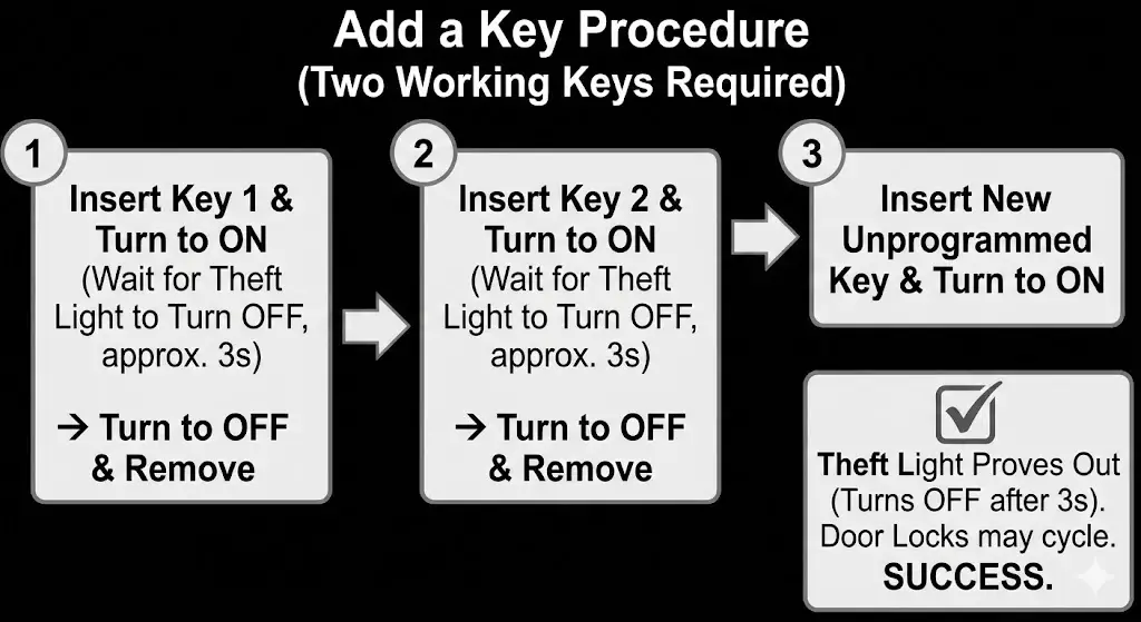
The "Add a Key" Method (No Tools Required)
This procedure allows an owner to program a third key if they already possess two working original keys. This feature relies on the vehicle's self-programming logic.23
Applicability: Most Ford vehicles 1998–2010 (approx). Note that some fleet vehicles have this feature disabled via the "Customer Spare Key Programming" bit in the BCM configuration.
Workflow:
- Insert Key 1 (Working): Turn ignition to ON (Run). Watch the theft light. Wait for it to turn OFF (approx. 3 seconds).
- Remove Key 1: Turn ignition OFF and remove the key.
- Insert Key 2 (Working): Within 5 seconds, insert Key 2 and turn to ON. Wait for the theft light to turn OFF (approx. 3 seconds).
- Remove Key 2: Turn ignition OFF and remove the key.
- Insert Key 3 (New/Unprogrammed): Within 10 seconds, insert the new key and turn to ON.
- Verification: The theft light should illuminate for 3 seconds and then turn OFF, indicating the key has been accepted. The door locks may cycle on some models to confirm success.
The "All Keys Lost" Method using FORScan
FORScan has democratized PATS programming, allowing independent shops and enthusiasts to perform functions previously restricted to the $5,000 Ford IDS system.
Prerequisites:
- Hardware: An OBDII adapter with MS-CAN/HS-CAN switching capability (e.g., OBDLink EX).
- Software: FORScan (Windows version recommended) with an Extended License (required for PATS access).
- Keys: Two valid, cut transponder keys.
Workflow:
- Connection: Connect OBDII adapter to the vehicle and laptop. Launch FORScan and connect to the vehicle. Confirm all modules are read (PCM, IPC, BCM).
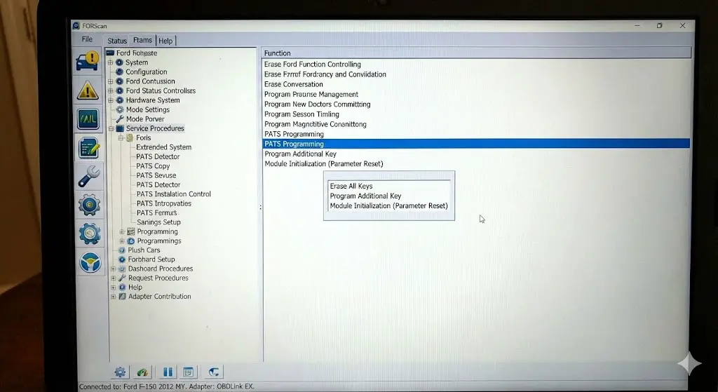
- Access PATS: Navigate to the Service Functions tab (Wrench Icon). Locate "PATS Programming". Depending on the vehicle, this may be listed under "IC" (Instrument Cluster), "PCM", or "BdyCM".
- Security Access (The 10-Minute Wait):
- Select "Erase All Keys".
- The system will initiate "Security Access". On older "Timed Access" systems, FORScan will display a timer. You must wait 10 minutes (600 seconds). This is a hardware-enforced delay to deter theft. Do not let the laptop sleep.
- On newer "Coded Access" systems, FORScan may calculate the Incode/Outcode automatically.
- Erase Execution: Once access is granted, confirm the "Erase All Keys" command. The keys are now wiped.
- Programming Cycle:
- Turn Ignition OFF.
- Insert Key 1: Turn to ON. The theft light may flash (Code 21 - Not enough keys). Wait 3 seconds. Turn OFF.
- Insert Key 2: Turn to ON. Wait 3 seconds. The theft light should prove-out (turn off).
- Parameter Reset (If Needed): If the keys are programmed but the car won't start, return to the PATS menu and select "Module Initialization" or "Parameter Reset" to re-sync the PCM and Cluster.21
Resetting Intelligent Access (PEPS) Systems
For modern vehicles (2011+) with Push-Button Start, there is no ignition cylinder. The "key" is a fob.
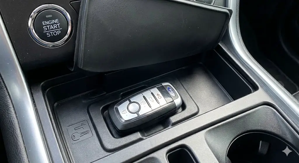
The Backup Slot:
Every PEPS vehicle has a "dead fob" slot designed to read the transponder even if the fob battery is dead. Locations include:
- Fusion/Mondeo: Inside the center console or under the cupholder rubber mat.
- F-150: Under the rubber mat in the storage tray or inside the console "media hub".
- Mustang: In the cupholder.
Reset/Program Procedure:
- Place the new unprogrammed fob in the backup slot.
- Perform the "Door Lock Dance": (Specifics vary by model, but generally:)
- Press the UNLOCK button on the door.
- Press the START button (without brake) to cycle ACC-ON-OFF a specific number of times (often 8 times).
- The door locks will cycle, indicating programming mode.
- Authentication: Press a button on the new fob. The locks cycle again to confirm storage.28
- MyKey Reset: If a key has "MyKey" restrictions (speed limiter), the only way to remove them without the Admin key is to perform an "Erase All Keys" via FORScan and reprogram two fobs. This defaults the system back to Admin status.31
Advanced Topics – Remote Start and Aftermarket Integration
The intersection of factory security and aftermarket convenience is a frequent failure point. Remote starters must "bypass" the PATS system to function, which introduces complexity.
Bypass Module Theory
A remote starter must convince the PATS module that a valid key is present. In the past, this was done by hiding a physical spare key in a "coffin box" with a wire loop wrapped around the ignition. This method, known as Key Wrapping, is now obsolete and insecure.
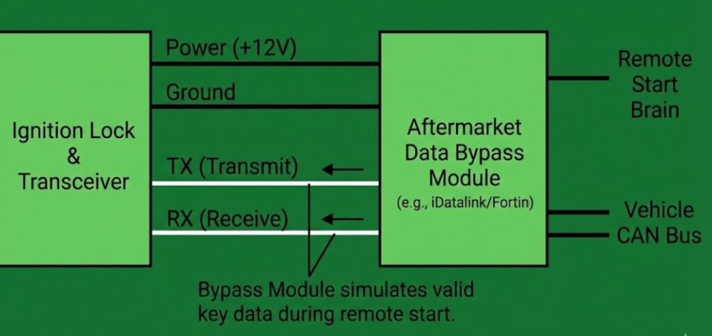
Modern systems use Data Bypass Modules (e.g., iDatalink, Fortin).
- Mechanism: These modules tap into the RX/TX (Receive/Transmit) data lines of the transceiver connector.
- Learning: During installation, the bypass module is "taught" the encrypted code of a valid key. It stores this code.
- Operation: When remote start is requested, the module disconnects the actual transceiver from the car (via a relay) and injects the stored digital key code directly into the PATS module's data wire.
The "Two-Master" Conflict
A common issue arises when a bypass module malfunctions or is poorly grounded. It may attempt to send data while the driver is simultaneously trying to start the car with a real key. This data collision confuses the PATS module, often triggering Code 13 (Signal Failure) or Code 16 (Data Link Error).
- Troubleshooting: If a vehicle with an aftermarket remote start exhibits intermittent PATS issues, the first diagnostic step is to physically unplug the bypass module to restore factory wiring integrity.32
Model-Specific Nuances and Case Studies
Ford F-150 (Gen 11: 2004–2008)
- System Type: Type E (PATS in PCM).
- Common Failure: The Instrument Cluster solder joints crack. This breaks the CAN communication path.
- Symptoms: Intermittent no-start, odometer reads "dashes", theft light flashes Code 16.
- Fix: Reflow solder on the cluster connector pins or replace the cluster (requires Parameter Reset).
Ford Focus (Mk2: 2005–2011)
- System Type: Type G (Distributed).
- Common Failure: Similar to the F-150, the cluster connector fails. Also, the ignition lock housing often wears out, preventing the key from turning or aligning the transponder correctly with the transceiver ring.
- Reset Note: These vehicles often require an "Incode/Outcode" calculation for programming, rather than just a timed wait, depending on the specific market (EU vs US).9
Ford Mustang (S197: 2005–2009)
- System Type: Type B/C (Smart Junction Box involvement).
- Water Damage: The S197 Mustang is notorious for water leaks in the passenger kick panel (Smart Junction Box area). Corrosion here can rot the CAN bus wires responsible for PATS communication, leading to a permanent theft light state.
FAQ and Myth-Busting
Q: Can I reset the PATS system by disconnecting the battery overnight?
A: No. This is the most persistent myth in automotive repair. The key data and security parameters are stored in Non-Volatile Memory (NVRAM). Like the hard drive in a computer, it retains data even when power is removed. Disconnecting the battery may reset the clock and radio presets, and it might stop a sounding alarm, but it will not allow an unprogrammed key to start the car.17
Q: Does the "10-minute reset" work without tools?
A: No. There is a widespread confusion between GM's "Passlock" system (which allows a 30-minute relearn without tools) and Ford PATS. On Ford vehicles, the "10-minute" wait is a security delay inside the software procedure when using a scan tool. You cannot simply leave the key in the ON position for 10 minutes to program a key. The only exception was the very early 1996-1997 Type A systems, which are virtually extinct today.36
Q: I have one key. Can I program a spare myself?
A: No. You need two unique keys to enter "Owner Programming Mode." If you have only one key, you are locked out of the self-service option and must use a diagnostic tool (locksmith or FORScan) to add the second key.
Q: My theft light flashes every 2 seconds when the car is parked. Is it draining my battery?
A: No. This is the normal "Armed" state. The LED consumes negligible power (milliamps). It indicates the immobilizer is active and monitoring.18
Conclusion
The Ford PATS system is a robust, evolving security architecture that balances effective theft deterrence with serviceability. While it can be a source of frustration—particularly the "Code 16" communication failures or the confusion surrounding 80-bit key transitions—it operates on logical, predictable rules.
For the technician or vehicle owner, the path to a successful reset lies in accurate identification: identifying the PATS generation (Type A-G), identifying the failure mode via Flash Codes, and utilizing the correct digital tools (FORScan/IDS). The era of analog "hot-wiring" is long past; modern automotive security demands a methodological approach rooted in data analysis and software capability. By following the protocols outlined in this report—specifically respecting the "Two Key" rule and the necessity of Parameter Resets after module swaps—most PATS issues can be resolved without the need for a dealership visit.


