Ford OEM Trailer Brake Controller Wiring Diagram: Easy Setup
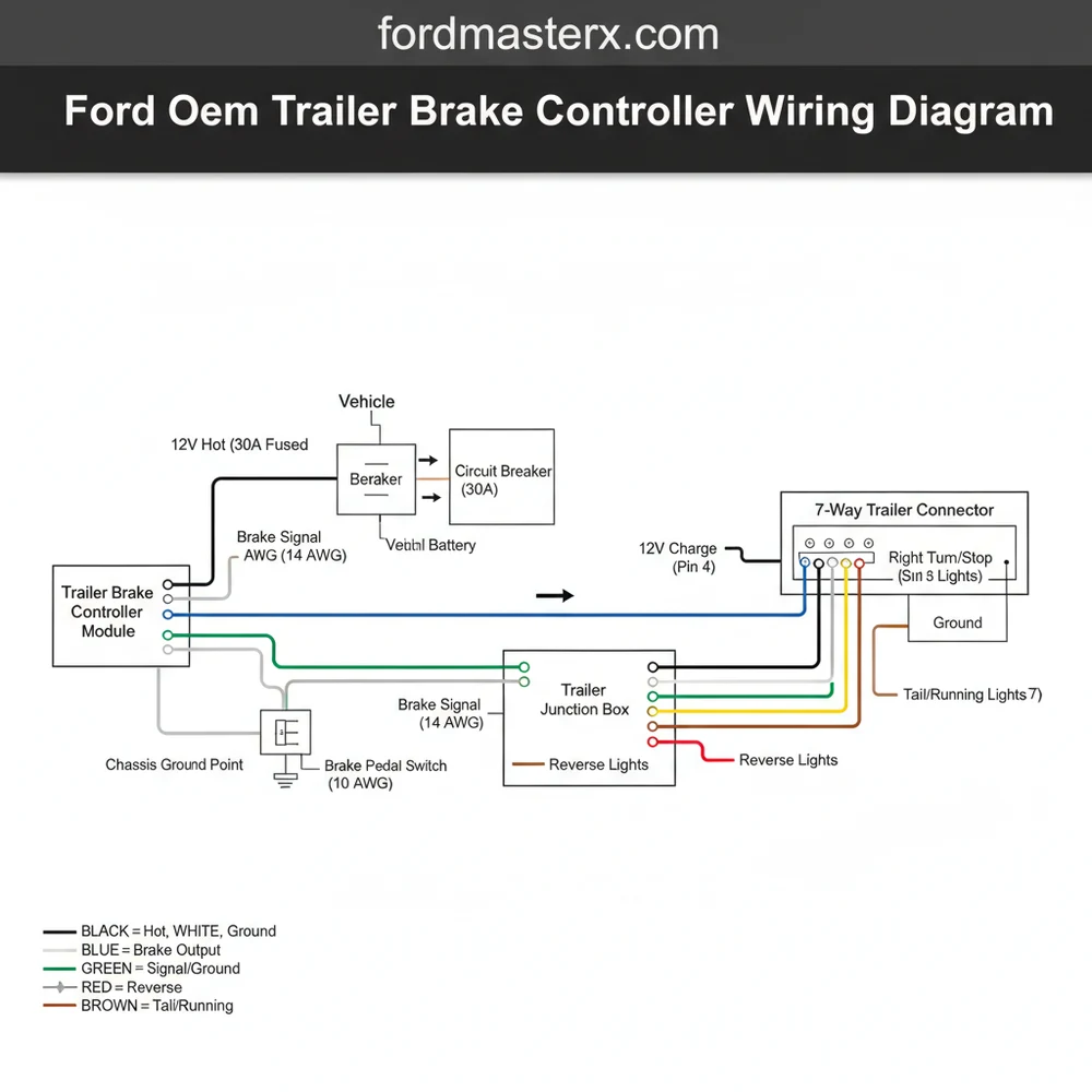
The Ford OEM trailer brake controller wiring diagram shows a harness connection involving a hot wire for 12V power, a ground wire for the circuit return, and a signal wire from the brake switch. Identifying the common terminal in the factory plug allows the controller to communicate with the vehicle’s computer for synchronized trailer braking.
📌 Key Takeaways
- The diagram identifies the specific pinouts for factory-integrated towing systems.
- The most important component is the pre-wired harness connector behind the dash.
- Always disconnect the battery to avoid blowing the high-amp trailer brake fuse.
- Use a multimeter to verify voltage on the hot wire before final assembly.
- Use this diagram when installing a new controller or fixing ‘Trailer Disconnected’ errors.
Installing a factory-integrated system requires precision, and having an accurate ford oem trailer brake controller wiring diagram is the foundation for a successful installation. Whether you are upgrading a base-model truck or replacing a faulty unit, understanding how the electrical signals flow from the brake pedal to the trailer axles ensures both safety and legality on the road. This guide provides a comprehensive breakdown of the wiring architecture, color codes, and terminal locations. You will learn how to identify each pin, verify voltage levels, and ensure a secure connection that integrates seamlessly with your vehicle’s computer system.
Decoding the Ford OEM Trailer Brake Controller Wiring Diagram
The electrical architecture of a Ford trailer brake controller (TBC) is significantly more complex than a simple on-off switch. The system relies on a dedicated harness, usually tucked behind the dashboard or integrated into the center console area. The ford oem trailer brake controller wiring diagram typically illustrates a 14-pin or 5-pin connector, depending on the specific vehicle generation. Unlike aftermarket units that might use a generic “one size fits all” approach, the OEM diagram reflects a sophisticated interaction between the vehicle’s Body Control Module (BCM) and the anti-lock braking system.
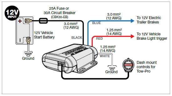
In a standard diagram, you will find four primary circuits that are essential for operation. The first is the hot wire, which provides constant 12-volt battery power to the module. This is typically a heavy-gauge wire, often 10 or 12 AWG, to handle the high current required to actuate electromagnetic trailer brakes. The second is the ground wire, which completes the circuit. In automotive applications, the chassis often acts as the return path, but the OEM harness includes a dedicated ground to prevent interference with sensitive digital signals.
The third component is the brake signal input. This wire carries the message from the brake pedal position sensor. Finally, the “output” or “feed” wire carries the modulated voltage to the 7-way connector at the rear of the truck. The diagram also accounts for illumination wires, which allow the controller’s display to dim and brighten with the rest of the instrument cluster. Understanding these labels—such as the common terminal for shared grounds or the specific pinouts for data communication—is vital before you begin splicing or pinning connectors.
Pin 1: Power (Hot Wire) – Large Gauge (Red/White)
Pin 2: Ground Wire – Large Gauge (Black/Blue)
Pin 3: Brake Lamp Feed (Violet/White)
Pin 4: Trailer Brake Control Output (Blue)
Pin 5: Illumination/Backlight (Violet/Grey)
Pin 6: CAN-BUS High (Data Link)
Pin 7: CAN-BUS Low (Data Link)
Pin 8-14: Auxiliary/Empty (Varies by Model)
Step-by-Step Installation and Wiring Guide
Following the ford oem trailer brake controller wiring diagram requires a methodical approach to ensure the electrical integrity of the vehicle. Before starting, ensure the vehicle is parked on a level surface and the negative battery terminal is disconnected to prevent accidental short circuits.
Working with vehicle electronics carries the risk of damaging the Body Control Module. Always use a digital multimeter rather than a test light, as test lights can pull too much current and fry sensitive circuits.
-
Step 1: Locate the OEM Harness
Most Ford trucks come “pre-wired” for a trailer brake controller. Reach behind the dash panel, usually to the right of the steering column or behind the coin holder tray. You are looking for a connector wrapped in foam tape. Match the physical connector to the one shown in your wiring diagram. -
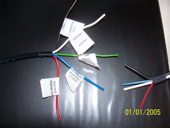
Step 2: Identify Wire Gauges and Colors
Inspect the wires entering the connector. The hot wire (power) will be the thickest wire in the bundle. In many Ford configurations, this is a 10-gauge wire. The ground wire should be of equal thickness. If you are using a conversion harness, ensure that the brass screw or terminal on your ground point is clean and free of paint to ensure a solid connection. -
Step 3: Test for Constant Voltage
Using your multimeter, set it to DC voltage. With the battery reconnected temporarily, touch the positive probe to the hot wire terminal and the negative probe to the common terminal or ground. You should see a reading of approximately 12.6V. This confirms that the trailer tow fuse in the engine bay is intact. -
Step 4: Verify the Brake Signal
While observing the multimeter, have an assistant press the brake pedal. The voltage on the signal wire should jump from 0V to vehicle voltage. This is the “trigger” that tells the TBC to start sending power to the trailer. In some diagrams, this is referred to as the brake switch input. -
Step 5: Connect the Module
Snap the OEM controller into the dash cavity and plug in the harness. Ensure the locking tab clicks firmly into place. If you are adding a harness where one didn’t exist, you may need to route a traveler wire—a term borrowed from residential wiring to describe the signal path—from the dash to the rear 7-way plug if the factory omitted the rear-to-front loom. -
Step 6: Software Activation
Unlike aftermarket controllers, a Ford OEM unit will not function simply by being plugged in. You must use a diagnostic tool (like FORScan or the dealership’s IDS) to enable the “Trailer Brake Control Module” in the vehicle’s computer. This allows the truck to recognize the hardware and display the gain settings on the dashboard.
In automotive DC systems, the ground wire serves as the return path for current. While house wiring uses a neutral wire to return current in an AC circuit, your truck uses the chassis and a dedicated ground wire to complete the loop. Always ensure the ground is as robust as the power wire.
Common Issues and Troubleshooting
Even with a perfect ford oem trailer brake controller wiring diagram, issues can arise during or after installation. One of the most common complaints is the “Trailer Disconnected” message appearing on the dashboard when a trailer is clearly attached. This is often not a fault of the controller itself, but a high-resistance connection in the wiring.
If the controller has no power, check the large J-Case fuse in the engine compartment fuse box. If the fuse is good but there is no voltage at the controller, there may be a break in the hot wire between the battery and the dash. Another frequent culprit is a poor ground. If the ground wire is connected to a rusted or painted surface, the circuit cannot complete, causing the module to behave erratically or fail to power up.
Using the diagram, check the continuity between the blue output wire at the dash and the corresponding pin on the 7-way plug at the bumper. If there is infinite resistance, the wire is severed. Additionally, ensure the common terminal inside the 7-way plug is clean; corrosion here is a leading cause of brake failure. If you see a “Module Fault” message, it usually indicates a communication error on the CAN-BUS lines (pins 6 and 7), suggesting the wires are swapped or the module needs to be flashed by a technician.
Tips and Best Practices for Towing Success
To ensure your trailer brake system remains reliable for years to come, follow these professional maintenance and installation tips:
Always use dielectric grease on the connector pins before plugging the harness into the module. This prevents moisture from causing pin corrosion, which is the number one cause of phantom “Trailer Disconnected” warnings.
First, always respect the wire gauge requirements. If you must extend any wires, never use a thinner wire than what is specified in the ford oem trailer brake controller wiring diagram. Using a 16-gauge wire where a 10-gauge is required can lead to overheating and significant voltage drop, resulting in weak trailer braking performance.
Second, when mounting a ground, avoid using a standard brass screw into thin sheet metal if possible. Instead, utilize an existing factory ground stud that is welded to the frame or a thick structural member. This ensures a low-resistance path for the high current the brakes demand.
Third, verify your trailer’s wiring matches the truck’s output. Sometimes, trailer manufacturers use different color codes for the traveler wire or signal feed. Always test the pins at the bumper with a multimeter to confirm that the “Blue” wire on your truck’s diagram actually aligns with the “Brake” pin on the trailer plug.
Finally, consider the cost-benefit of OEM versus aftermarket. While OEM controllers require computer programming, they offer “proportional braking,” which uses the truck’s internal transducers to apply trailer brakes with the same intensity as the truck’s brakes. Aftermarket “timed” controllers simply ramp up power over time, which is less safe and harder on your equipment. Investing the time to follow the ford oem trailer brake controller wiring diagram and installing a factory unit provides a much smoother, safer towing experience.
By carefully following the pinouts, verifying your voltage readings, and ensuring a solid ground wire connection, you can confidently tow heavy loads knowing your braking system is integrated perfectly with your Ford vehicle. Accuracy during the wiring phase is the best way to prevent roadside emergencies and ensure your trailer responds instantly to every tap of the brake pedal.
Frequently Asked Questions
Where is the Ford OEM trailer brake controller located?
The controller is typically located in the center stack of the dashboard or just to the left of the steering wheel. On most Ford trucks, you will find a plastic cubby or blank panel that can be removed to reveal the factory-installed wiring harness waiting for the OEM module.
What does this wiring diagram show?
The diagram illustrates the electrical path from the vehicle’s battery and brake pedal to the trailer connector. It details the traveler wire for signal transmission and how the module integrates with the truck’s computer to provide proportional braking force based on the vehicle’s current speed and braking pressure.
How many wires does the Ford trailer brake controller have?
The OEM controller usually features a 4-pin or 5-pin configuration within a single plug. This includes a dedicated hot wire for constant power, a ground wire, a brake input signal, and an output lead that sends controlled voltage back to the 7-pin trailer plug at the bumper.
What are the symptoms of a bad trailer brake controller?
Common symptoms include intermittent braking, a ‘Trailer Disconnected’ message despite being plugged in, or the trailer brakes locking up instantly. These issues are often caused by a loose common terminal connection or a short circuit in the wiring harness that prevents the module from regulating voltage properly.
Can I install this brake controller myself?
Yes, installing a Ford OEM controller is a popular DIY project because most trucks come pre-wired. After plugging the module into the factory harness, you will likely need to use a tool like FORScan or visit a dealership to program the truck’s computer to recognize and activate the new hardware.
What tools do I need for this installation?
You will need plastic trim removal tools to pop off the dashboard panels without scratching them, a small socket set (7mm or 10mm), and a flashlight. A multimeter is also helpful to confirm that the neutral wire return and power leads are functioning before you finish the reassembly.


