Ford Manual Locking Hubs Diagram: Comprehensive Guide
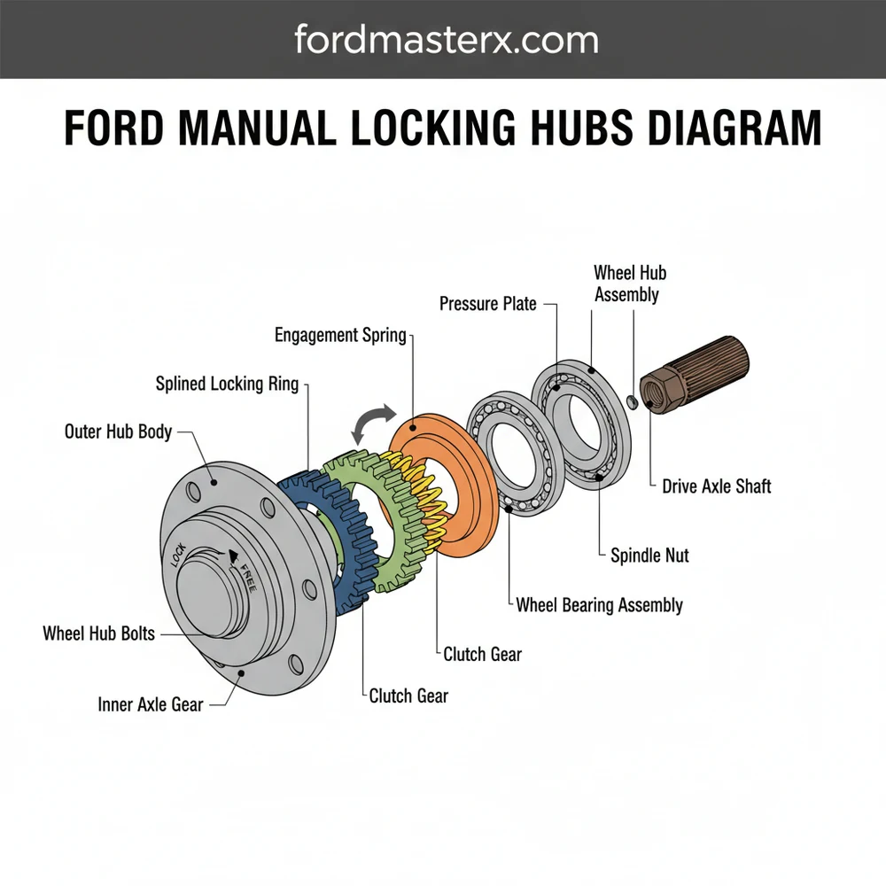
A Ford manual locking hubs diagram displays the internal components of the wheel hub assembly, including the dial, spring, and clutch gear. This visual layout helps owners understand how the system configuration engages the front axle to the wheels, ensuring proper torque transfer during four-wheel drive operation on various terrains.
📌 Key Takeaways
- Illustrates the mechanical connection between the axle and the wheel hub.
- Crucial for identifying the clutch gear and return spring for proper function.
- Always ensure the dial is fully rotated to the Lock or Free position to prevent damage.
- Apply high-quality waterproof grease to the internal structure for longevity.
- Use this diagram when servicing 4×4 engagement issues or replacing old hubs.
For Ford truck owners, maintaining a reliable four-wheel-drive system is paramount for both off-road performance and winter safety. Understanding your vehicle’s frontend begins with a clear ford manual locking hubs diagram. Whether you are performing a routine service, replacing worn-out seals, or troubleshooting a failure to engage, having a visual schematic of the hub’s internal structure is the difference between a successful repair and a costly mistake. This guide provides a comprehensive overview of the components, layout, and assembly process, ensuring you have the technical blueprint needed to master your truck’s 4×4 configuration and keep your wheels turning in the toughest conditions.
Decoding the Ford Manual Locking Hubs Diagram
The internal structure of a Ford manual locking hub is a masterpiece of mechanical engineering designed to bridge the gap between the axle shaft and the wheel hub. When you look at a standard schematic, you are viewing an “exploded” perspective of the assembly. This layout is essential because it shows the specific order in which components must be stacked to ensure the locking gear meshes correctly with the splines.
At the outermost layer of the system is the hub cap and selector dial. This is the user interface where you physically turn the dial from “Free” to “Lock.” Moving inward, the blueprint reveals a series of critical components: the retainer ring, the internal snap ring, and the main body assembly. The heart of the hub consists of the drive gear, the pressure spring, and the cam assembly. In many Ford configurations, particularly on heavy-duty models like the F-250 or F-350, you will also notice a thick axle shaft snap ring that prevents the entire assembly from migrating outward during operation.
Most Ford manual hubs utilize a “fail-safe” mechanical design. Even if the vacuum system fails on pulse-vacuum models, the manual override allows the driver to bridge the connection between the drivetrain and the wheels physically.
The configuration of these parts varies slightly depending on whether your truck uses the classic Dana 44 or Dana 60 axles, or the newer Ford-designed Sterling front ends. However, the fundamental overview remains the same: a spring-loaded gear moves laterally to bridge the gap between the outer hub shell (bolted to the wheel) and the inner splined shaft (connected to the differential). The diagram highlights these contact points, showing exactly where lubrication is required and where friction must be minimized.
[DIAGRAM PLACEHOLDER: EXPLODED VIEW OF FORD MANUAL HUB]
1. Cap Assembly (Selector Dial)
2. Cap Screws (Usually 3 or 6)
3. Large Wire Retaining Ring
4. Hub Body / Internal Gear
5. Pressure Spring
6. Locking Gear / Cam
7. Internal Snap Ring
8. Axle Shaft Snap Ring (Deepest Component)
Step-By-Step Guide: Interpreting and Using the Schematic
Reading a ford manual locking hubs diagram effectively requires an understanding of how mechanical motion translates into four-wheel-drive engagement. Follow these steps to use your schematic for a full tear-down and reassembly.
- ✓ Step 1: Preparation and Tool Selection – Before opening the hub, gather the tools identified in the blueprint. You will typically need a T25 or T27 Torx bit for the cap screws, a set of high-quality internal and external snap ring pliers, and a clean workspace. Refer to the overview to ensure you have replacement seals if the diagram indicates they are non-reusable.
- ✓ Step 2: External Cap Removal – Using your Torx bit, remove the screws holding the dial cap to the hub body. As you pull the cap away, note the layout of the O-ring or gasket. If this seal is damaged, moisture will enter the system, leading to corrosion and eventual failure.
- ✓ Step 3: Disengaging the Large Retainer – Look for the large wire ring seated in a groove on the inner diameter of the hub bore. This is often the most frustrating component to remove. Use a small flat-head screwdriver to pry one end up, then work your way around as shown in the schematic.
- ✓ Step 4: Extracting the Hub Body – Once the retainer is out, the main hub body should slide out. If it is stuck, it is likely due to old, hardened grease. Refer to the structure diagram to see where the internal splines meet; a gentle pull with a pair of pliers on the center section usually does the trick.
- ✓ Step 5: Inspecting the Internal Snap Ring – Deep inside the hub, you will see a snap ring on the end of the axle shaft. The blueprint highlights this as a critical retention point. Without this ring, the axle shaft can pull back into the knuckle, causing the hub gears to misalign.
- ✓ Step 6: Cleaning and Component Inspection – Clean every component with a mild solvent. Compare the physical parts to the ford manual locking hubs diagram to check for chipped gear teeth or a collapsed pressure spring. A spring that has lost its tension will not have the force required to push the locking gear into place.
- ✓ Step 7: Reassembly and Lubrication – Apply a light coat of high-temperature wheel bearing grease. A common mistake is “over-packing” the hub. Too much grease creates a vacuum seal that prevents the gears from sliding. Follow the schematic in exact reverse order to reassemble.
Never use heavy chassis grease inside a manual locking hub. In cold temperatures, heavy grease can solidify, preventing the spring from engaging the gears, effectively leaving you in two-wheel drive when you need 4×4 most.
Common Issues and Troubleshooting the Hub System

Even with a perfect ford manual locking hubs diagram, mechanical issues can arise. The most frequent problem is a “frozen” selector dial. This occurs when the outer seal fails, allowing salt and water to corrode the aluminum-to-plastic interface. If the dial won’t turn, do not force it with pliers, as you will likely snap the plastic internal cam.
Another common issue is gear grinding. This typically happens when the internal pressure spring (labeled in your schematic) weakens or when the axle shaft snap ring has popped off. If the gears are only partially engaged, they will “skip” under load, creating a loud metallic ratcheting sound. By consulting the layout, you can identify if the component responsible for lateral movement—the cam assembly—is properly indexed. If you notice gear teeth are rounded off, the system requires a full replacement of the internal gear set to restore 4WD functionality.
If you are having trouble getting the large internal snap ring back into its groove, have an assistant push the axle shaft forward from behind the steering knuckle. This exposes the groove and makes installation much easier.
Tips & Best Practices for Hub Maintenance
To maximize the lifespan of your Ford’s 4WD configuration, proactive maintenance is key. One of the best practices is to engage your hubs at least once a month, even if you don’t need four-wheel drive. This keeps the grease distributed and prevents the internal structure from seizing due to inactivity. When you consult your overview, note the locations of the rubber seals; these should be inspected annually for dry rot.
When it comes to component quality, many enthusiasts prefer aftermarket manual hubs from brands like Warn or Mile Marker if the OEM Ford units fail. These often feature an all-metal structure that is more durable than the plastic-heavy stock designs. Regardless of the brand, always refer back to your schematic during the install to ensure the thrust washers are placed in the correct sequence. Incorrect washer placement can lead to excessive end-play, which destroys wheel bearings over time.
Finally, keep your blueprint handy during the winter months. Road salt is the primary enemy of the manual hub. Rinsing the frontend of your truck after driving on salted roads can prevent the corrosion that leads to the selector dial sticking. By following the ford manual locking hubs diagram and performing these simple maintenance steps, you ensure that your truck remains a reliable workhorse for years to come, ready to tackle any terrain at the turn of a dial.
In conclusion, the ford manual locking hubs diagram is an indispensable tool for any DIY mechanic. By understanding the layout, respecting the structure of the system, and following a methodical repair process, you can maintain peak performance in your vehicle’s four-wheel-drive assembly. Whether you are dealing with a simple stuck dial or a complex internal gear failure, a clear schematic is your best guide to a job well done.
Step-by-Step Guide to Understanding the Ford Manual Locking Hubs Diagram: Comprehensive Guide
Identify the main components in the diagram to understand the hub configuration.
Locate the outer cap bolts or snap ring that secures the assembly to the wheel.
Understand how the internal clutch gear slides to engage the axle splines when locked.
Apply a thin layer of waterproof grease to the moving parts within the system.
Verify that the dial rotates smoothly between the Lock and Free positions after assembly.
Complete the installation by torquing the outer bolts to the manufacturer specifications.
Frequently Asked Questions
Where is the locking hub located?
It is located on the front wheel ends of Ford 4×4 vehicles. The manual hub assembly is bolted directly to the wheel bearing housing, accessible from the exterior center of the wheel rim. This location allows drivers to manually rotate the dial to engage or disengage the front axles.
What does this hub diagram show?
The diagram illustrates the complete internal structure and layout of the hub assembly. It details how the component configuration works, showing the relationship between the splined drive gear, the tension spring, and the outer dial that controls whether the hub is locked into the axle or free-spinning.
How many parts are in the hub assembly?
A typical manual hub system consists of about 10 to 15 individual parts. Key components include the outer cap, internal clutch gear, large and small snap rings, a heavy-duty return spring, and various gaskets or O-rings designed to keep debris and water out of the axle assembly.
What are the symptoms of a bad locking hub?
Symptoms include difficulty turning the manual dial, grinding noises from the front end, or the 4×4 system failing to engage. If internal components are worn or seized, the vehicle will remain in two-wheel drive despite the transfer case being engaged, often requiring a full teardown and inspection.
Can I replace these hubs myself?
Yes, replacing manual locking hubs is a straightforward DIY task that usually requires only basic hand tools. Most units are held in place by a series of bolts or a large snap ring. Replacing them yourself saves on labor costs and ensures your 4WD system remains dependable.
What tools do I need for hub service?
You will typically need a set of Allen wrenches or a socket set to remove the outer cap, snap ring pliers for the internal retainers, and clean rags for wiping down components. High-quality marine-grade grease is also essential for lubricating the internal structure during the reassembly process.


